

BeetonCade
When lockdown hit for the first time in March 2020 I was already beginning to build stuff from wood. My collection of tools was growing at pace and I was beginning to get the hang of not cutting parts of my anatomy off.
Skip forward a couple of months to May. I had already completed a couple of interesting builds, including a snazzy cat bench for Gus.

The rest of this text is copied from my blog at the time.
Contents
- Starting at the End
- The Beginning
- PREVIOUSLY UNTITLED BUT NOT UNLOVED
- Deeper into DISASTER!
- MAKING MISTAKES IS FUN!
- SPEAKER SURGERY!
- TO DO: FLOORS AND DOORS.
- A MIXED BAG OF JOBS
- ARTISTIC SENSE IS TINGLING!
- NA NA, NA NA, NA NA, NA NA. NA NA, NA NA, NA NA, NA NA. SIDE ART!
- I SEE THROUGH YOU
- I LOVE THE SMELL OF SOLDER IN THE EVENING
- ITS THE END!
- An Additional Arcade Addendum
Wednesday, 6 May 2020
Starting at the End
I built this arcade cabinet for two very young great-nephews of mine. A year or two ago I built another bartop arcade cabinet for myself, a bigger, heavier, uglier version of what you see here. I brought that machine along to a family BBQ and introduced my nephews to it. They turned into arcade limpets.
A few months ago I was toying with the idea of building another cabinet. I had sold the old one and was missing the fun of building something cool. I mentioned this in passing to my nephews mum and they instantly asked if I was going to build it for them! Cheeky tikes! This idea burrowed into my brain and took root. I took stock of what I would need and found that I already had a lot of the parts, which I will cover in detail later.
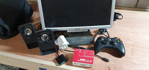
The first part I needed was the screen. I knew I wanted it to be two-player, to avoid as many arguments as possible. I chose a spare Acer 19″ 16:9 LCD monitor. It had been unused for some time in my mancave. I had a couple of spare arcade Zippy sticks which I had salvaged from my very first arcade cabinet build way back when, and a box of buttons I thought would suffice. All I really needed was a Raspberry Pi and a few cables. And some wood. And some paint. And a LOT of spare time.
All of this thinking went on around January. I took this photo on the 18th of January when I was trying to decide what to make it out of.
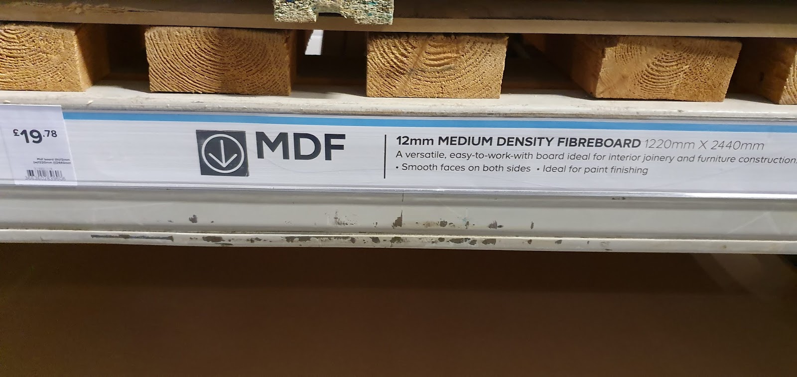
I chose 12mm MDF. I knew I would not be able to use T-molding, that would drive the cost up. And I knew I wanted to keep the weight down, the last cabinet was not at all portable, despite being a bartop. It was larger and the wood was fifty percent thicker. 12mm MDF is still strong enough in such a small box.
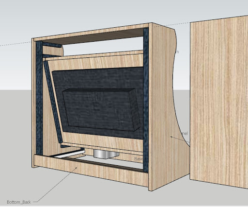
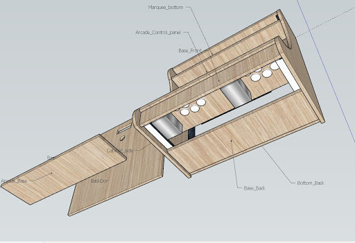
Next, I tore down the screen, measured it, and started adding parts to a Sketchup plan. The idea was to make it as small as possible with all the parts that I had.

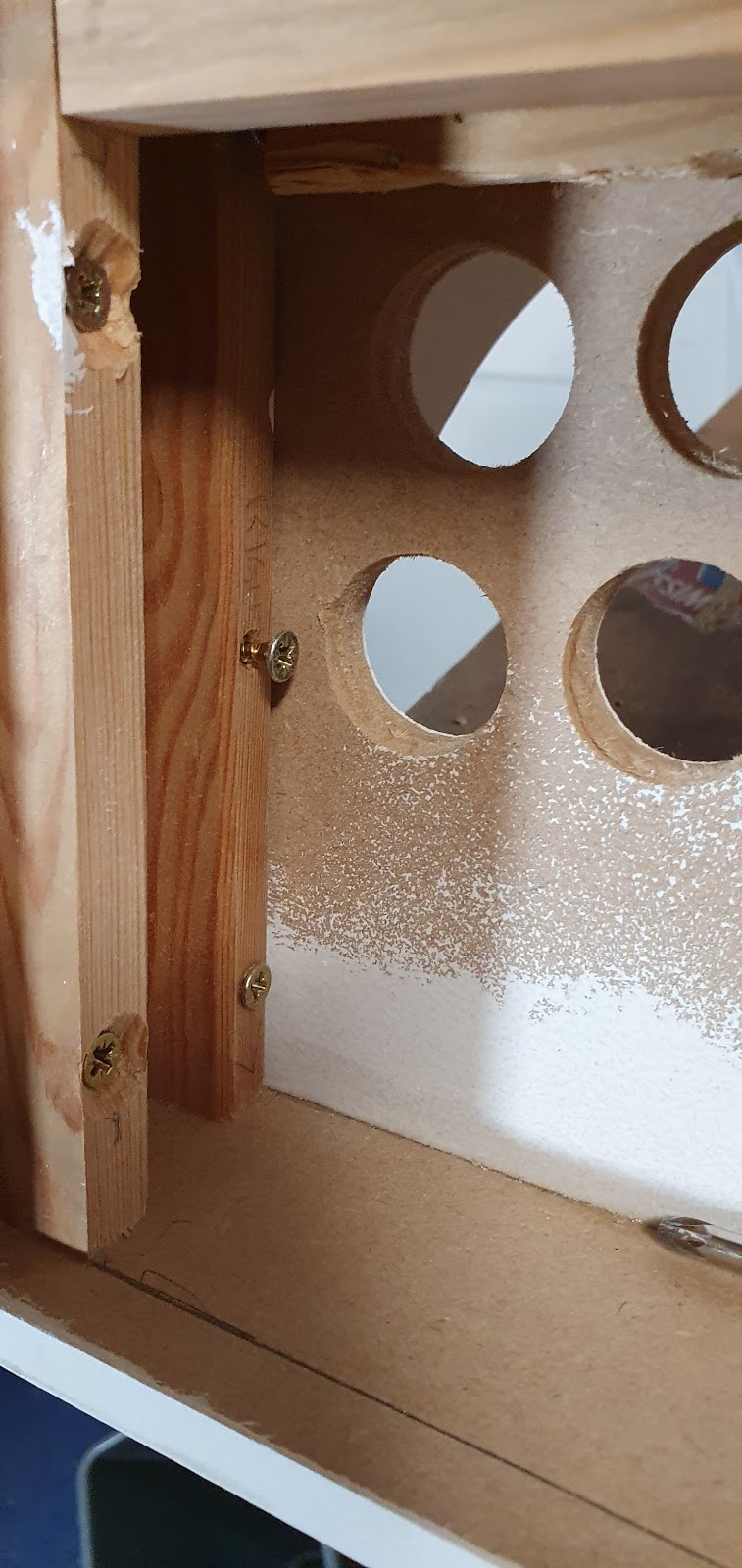
I made sure there was access below as well as the back as I knew the room beneath would be extremely tight.
I finished designing it, saved the plan, and then put it away and forgot about it for a while.
Then, one random day, about a month later, I decided to go and buy some wood to build a cabinet in the utility room (not an arcade cabinet). Having designed that cabinet in Sketchup too I took a look at the arcade cab design, which also included a cut list. I printed it out and drove off to B&Q. There, as well as the 18mm MDF for the utility room cupboard (which I dropped on my foot, somehow it didn’t break a bone) I picked up a sheet of 12mm too and got it broken down to the right widths. I drove home, stacked it against a wall, and forgot about it again!
Time is always at a premium. I knew I would get round to it eventually. But realistically it would take me months.
March rolled around and we all know what happened then! Suddenly I had more free time than I’d had forever. And, after making a cat bench…

… I decided it would be really nice for my nephews to have an arcade machine during lockdown.

And so, it began!
The beginning!
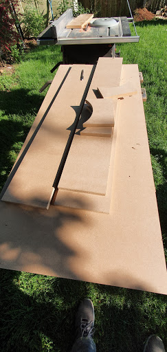
All of the MDF I had was cut to the width of the cabinet. I needed to cut these larger boards down to the individual parts of the cabinet.

I cut them close to the final size and then took them to my, pretty bad, table saw. With some messing about I managed to get everything almost exactly right.
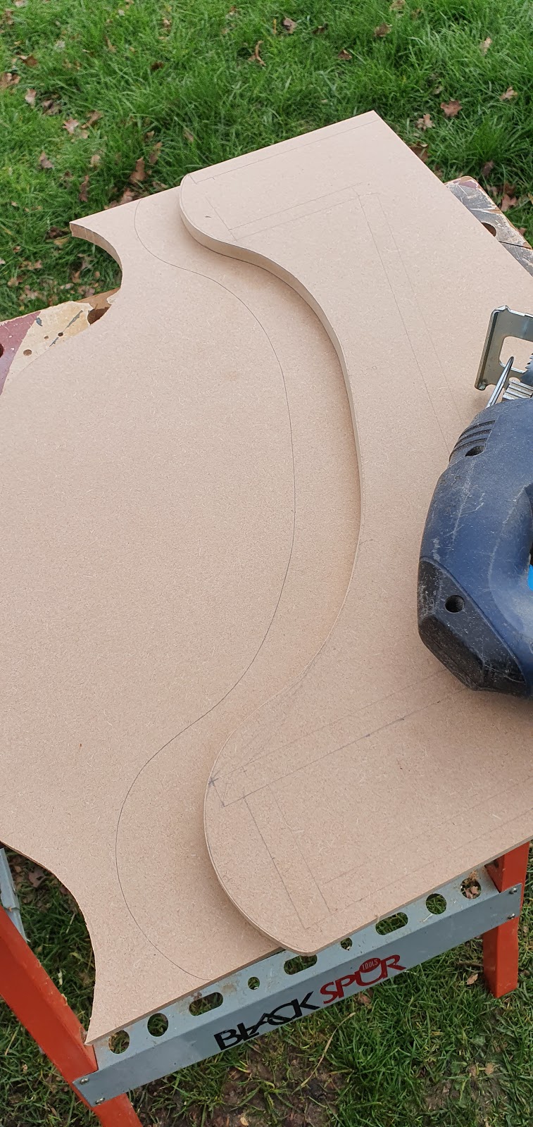
Next, I took the board that had been cut to the height of the cabinet and marked out the contour of the side panels. These I cut out with a jigsaw and then sanded to the final shape. This is where MDF comes into its own. It’s so easy to shape with a file or sandpaper.

Once I had that panel how I wanted it I lined it up with the other side and drew a line which I then jigsawed. I didn’t saw directly on the line, but next to it.
Then I clamped the two pieces together and ran a router around the contoured part with a pattern bit to make them identical.

If you zoom in on this last pic you can see where I started to set out the lines for all of the connecting panels

Here is the pile of connecting bits. Top of marquee, bottom of marquee, bezel, control panel, front of control panel, rear door, base, bottom of back, back door. All the same width.

Next job was to cut a load of strips of wood, I had some nice pine spare, and make battens out of them. These needed to be very accurate. I wanted the joins to be exact without misaligned panels. A couple of mm out at one end could spiral out of control by the time I got to the other end. I drilled out holes in the battens on a drill press to make sure they were straight, then lined up where I wanted it to go on the board and used the drill I had used to make the holes as a centre punch. This meant the holes would be very accurate. I used my lovely wife’s hammer, she complains that I keep stealing it. Its a really nice hammer, perfect for this kind of work!

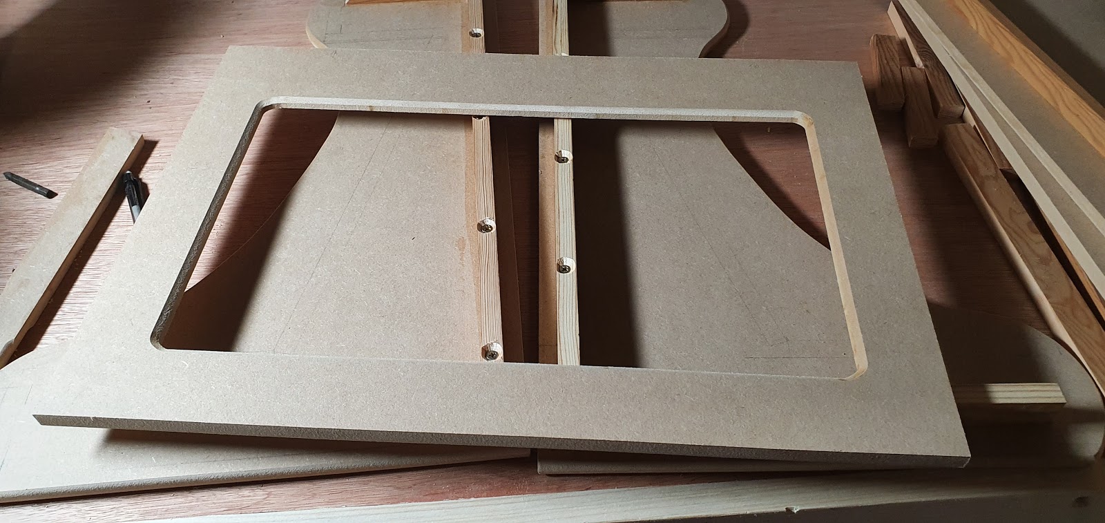
The battens for the top, rear and base were easy. But I ran into a small problem. The bezel panel I had was not square. I had spare wood, the whole thing used less than half of the 8ft by 4ft board, but I was reluctant to use that unless I really had to. I squared it up by trimming it on my table saw and decided to make it fit by adjusting the other parts around it. This meant fixing the remaining battens would have to wait till I finished the bezel.

And here it is! I was on song when I did this part. It came out the most perfect I could have wished and hoped for. When the screen is in position you cant see any of the metal housing and it is so exact that there is no loss of screen.
On the other side I placed the screen and traced around it with a pencil. I freehand routed a rebate for the screen to sit in, to bring it closer to the surface and give it somewhere to be supported. It looks a bit messy but somehow I nailed it first time. When I dropped the screen into place it slid in position without any play and was perfectly aligned. I have no idea how this happened. I wish I did.

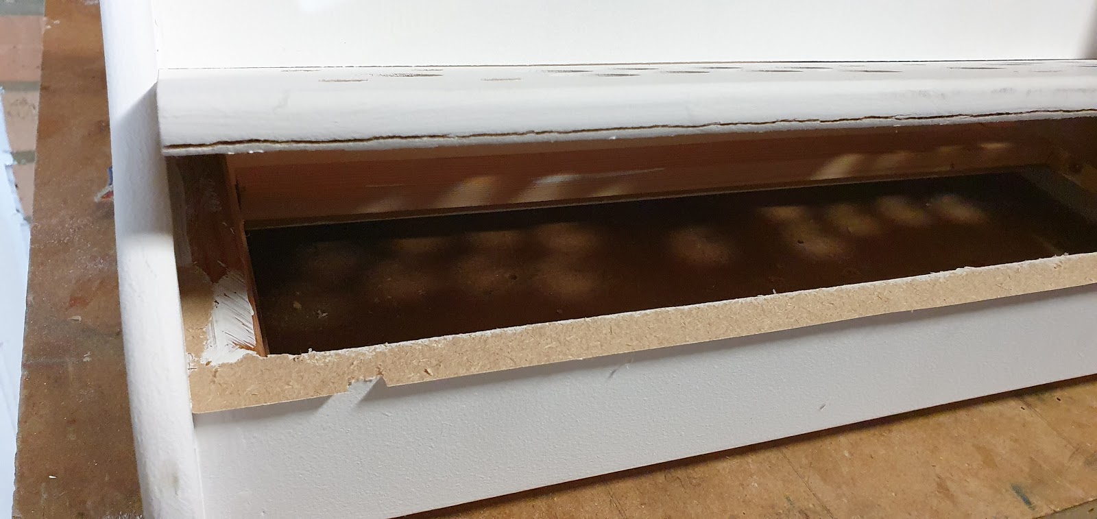
Now with the final dimensions of all the parts sorted I could finish the interior battening. Note the space between the top of the control panel and the base. It is the distance of the workings underneath the joystick, plus about 10mm spare.

On my last cabinet I had screwed the panels together from the inside into the MDF. This wasn’t ideal, MDF is ok when fixed into this way, but it isn’t great. I decided that, with the good access in the back and the base, I would glue this one together permanently.

I have a couple of Ryobi nail guns, they are superb. I used the 18 gauge one to pin nail the panels from the outside with plenty of PVA glue. These do leave small holes and blemishes, but I knew the finish on this would be paint so it wasn’t a problem. Large screw holes could be a problem if the filler pops out later on.

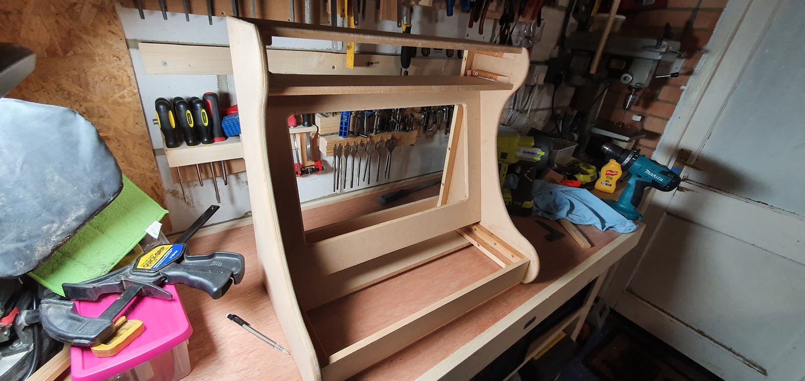
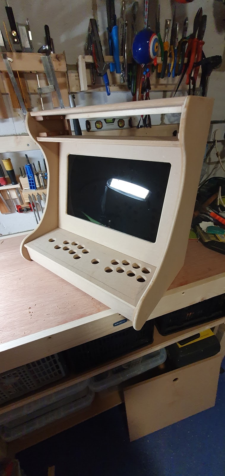
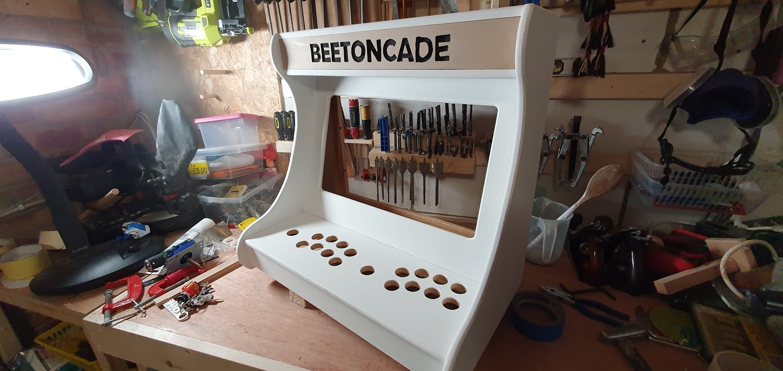
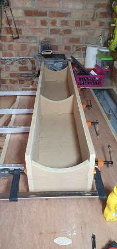
My first time seeing it put together like this I was a little shocked at how small it is. I did wonder if it would be big enough even for two small lads to be able to fit. But the control panel is actually the same width as my old bartop, so it’s fine.
PREVIOUSLY UNTITLED BUT NOT UNLOVED.
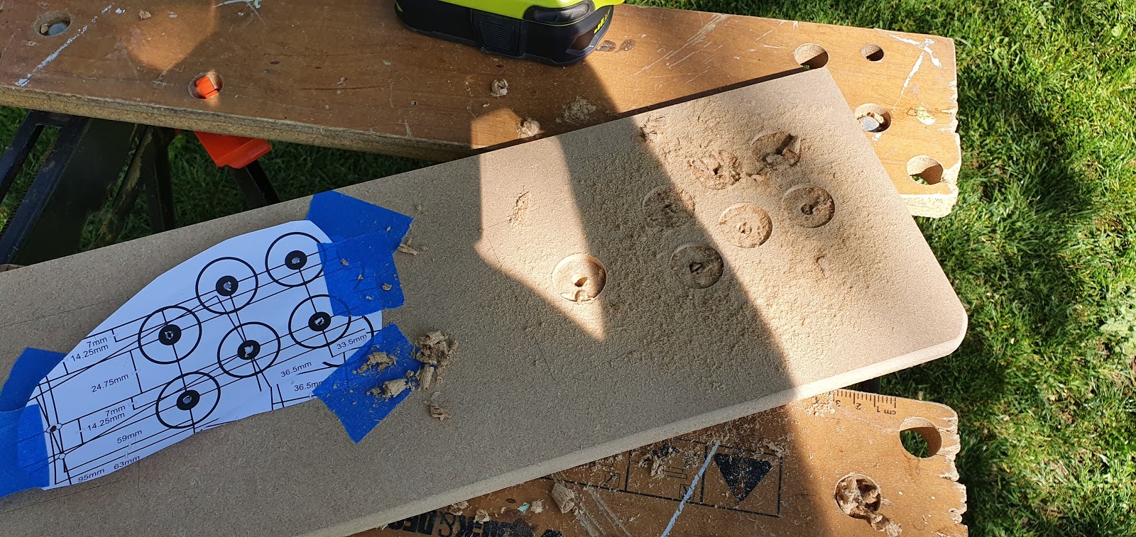
The next stage! The control panel is not fixed yet. I left it out to make drilling easier. I printed out templates and placed them on the panel and stood in arcade person pose to see how much room I would need either side. With the controls tilted slightly either side, it’s fairly roomy. Now, here begins a mistake. I won’t say what it is yet.

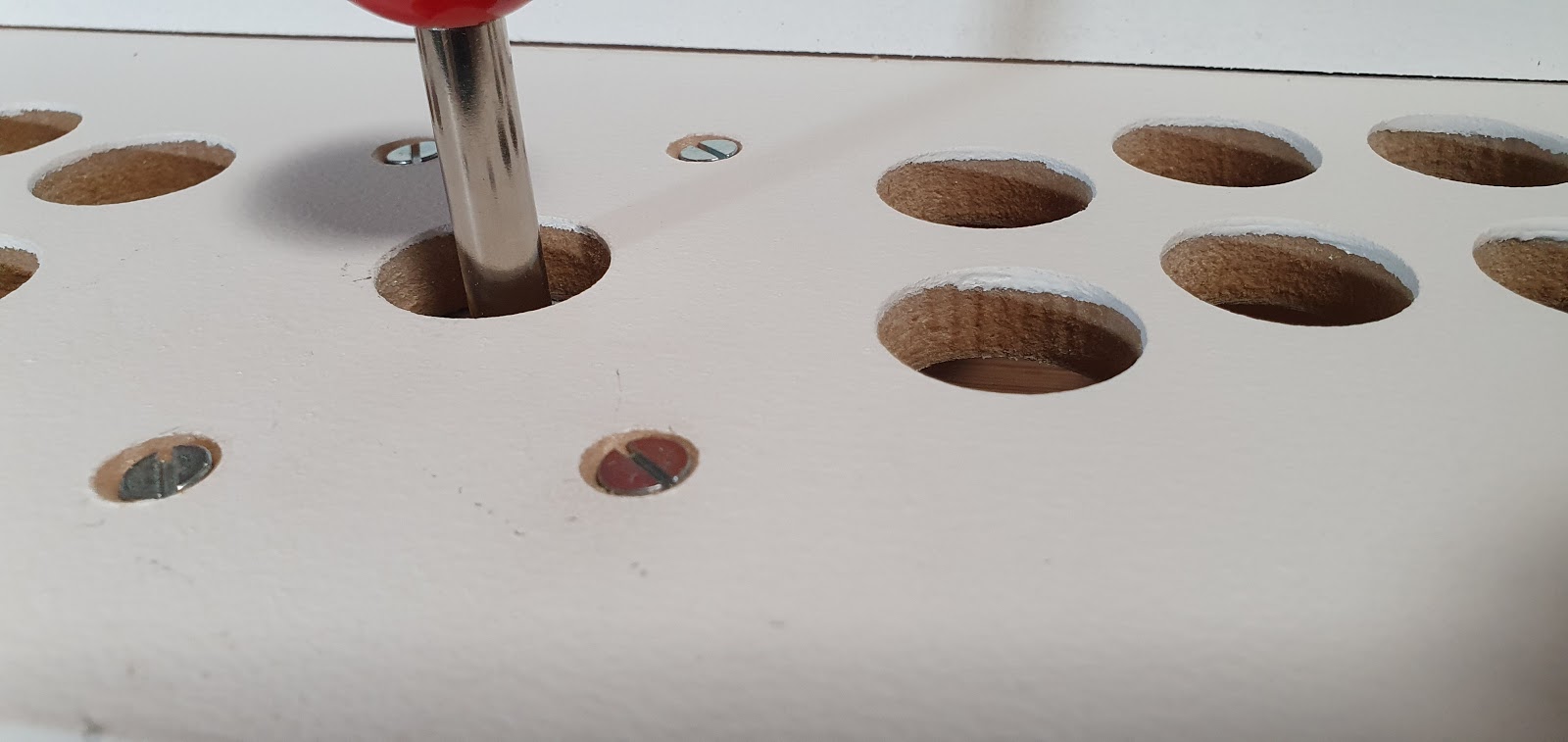
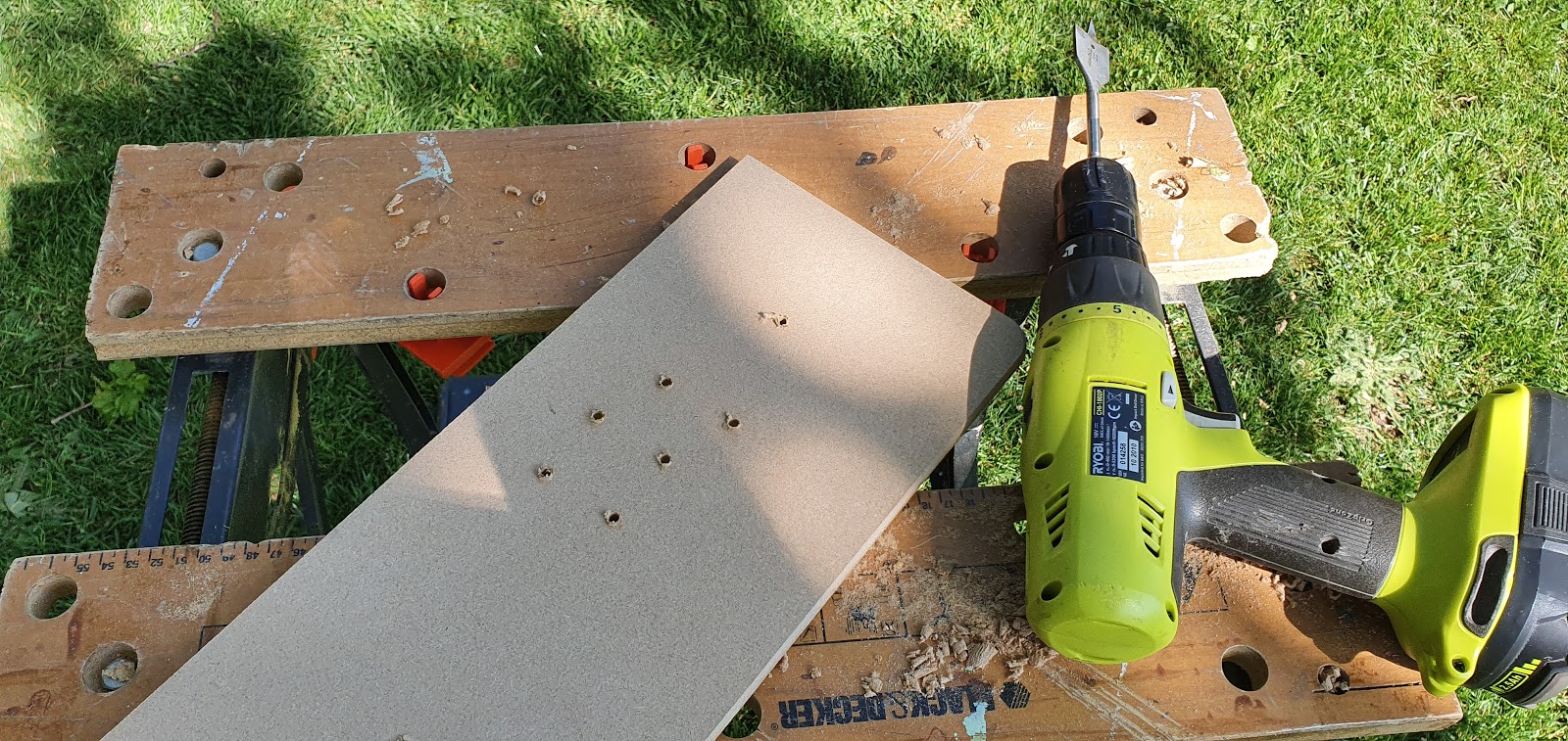
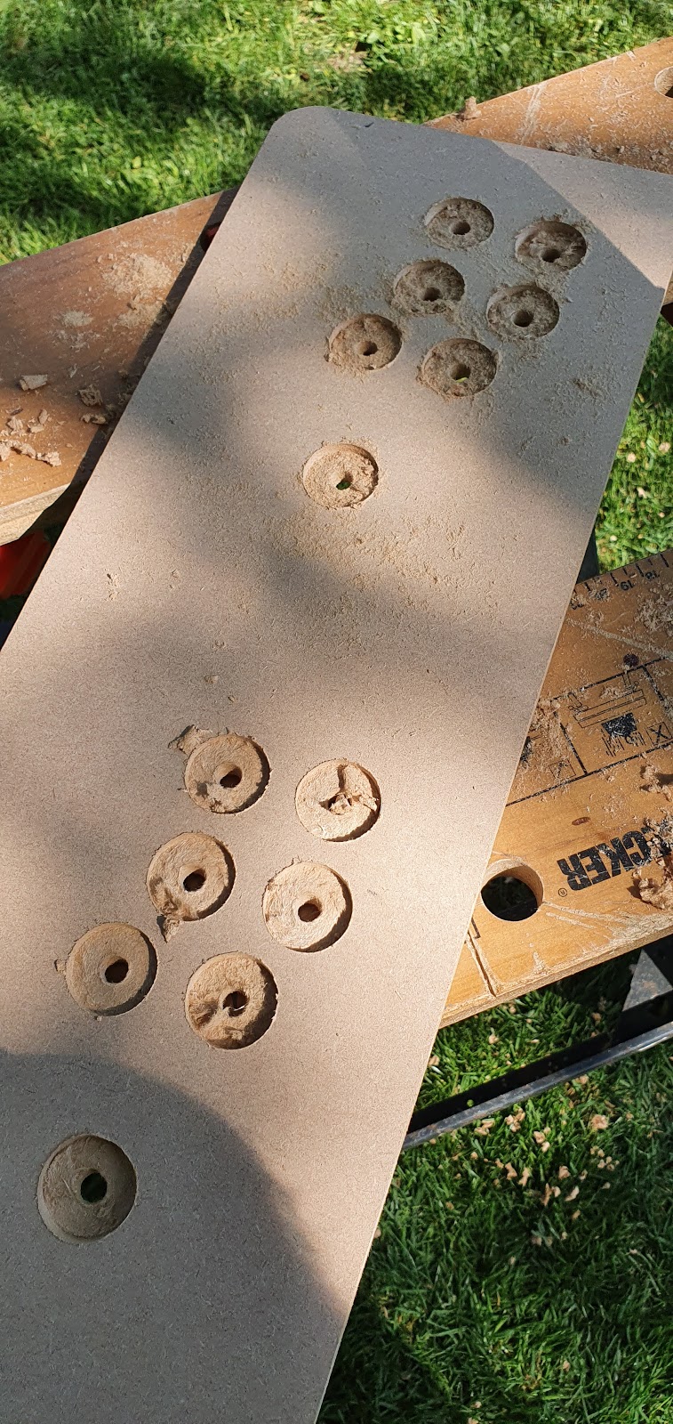
Drilling out a control panel is really nasty, soooo dusty. This has to be done outside and wearing a mask. The buttons I have for this are for 28mm holes. I centre punched all of them through the template, then drilled a small pilot hole. I used a spade bit for these holes, I would prefer a Forstner bit but I don’t have one that size. They are not as readily available in the UK for some reason. The spade bit did a decent job, as long as you drill partway through one side and then go at it from the other side it ends up fine.

Done. Joystick holes are also 28 mm.

I decided to sort out some mounting for the screen. The pale strip along the top has dire warnings about not touching it. I tried not to but almost every time I handled the screen I would accidentally grab it right there. It did no harm and I was never electrocuted. Probably a good idea not to though.

First time with the screen in place. I was very happy with this. Its TINY!
The mountings for the screen. They are all just screwed in, but the screws extend through those pine supports into the MDF, its a very strong fixing. Eight screws along the top. I put that many in as the bottom would not have a lot of room for many fixings. At the end of the build these are glued too. The top fixings are only against the metal of the screen housing and not touching that delicate strip. You can see the screen controls hanging down at the bottom, later these will be hot glued in place.

I followed some advice for sealing MDF edges. In the past I have sealed these with a 50/50 mix of PVA and water. Apparently sealing them with good ole primer does as good a job. It was ok, I think PVA is better, but there’s very little in it. Anyway. paint is starting to go on! All the edges for now.

Back door and control panel edges get the same treatment.

Nail holes being filled.

More filled nail holes around the bezel. A few of these were proud of the surface and needed a friendly tap to get them flush.

Base door, control panel (complete with mistake) and back door.

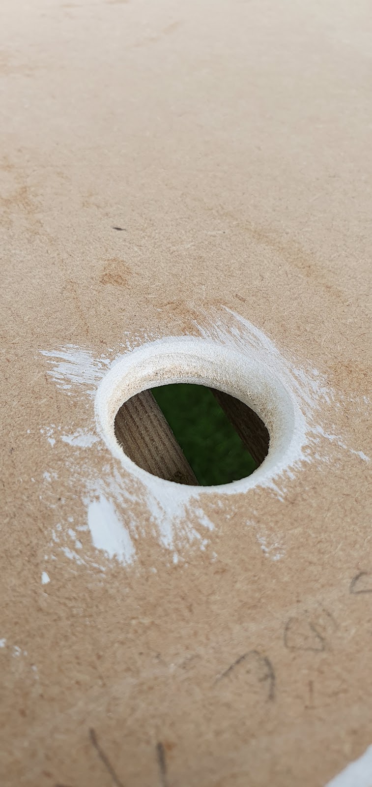
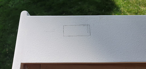
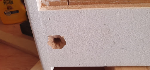
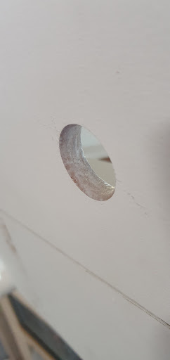
This was meant to be a finger hole for removing the back door, in the end it turned into a hole for the fan.
And the first coat of primer. I used Leyland Acrylic primer. It’s really nice to paint with. NOTHING will cover MDF in one coat, it’s incredibly absorptive?

Makes me sad seeing the wasted work going into that control panel.
I later added feet to the base. Two of them on this panel and two on the base door.

Getting all confident now. It’s looking pretty sweet.

And this is where I made the mistake I’d made earlier much worse. For some strange reason I decided to glue the control panel into place. No idea why. Probably just impatience and a little arrogance. Lesson learned.
Friday, 8 May 2020
Deeper into DISASTER! (I may be overselling this)
Last post I left you with the stark image of a control panel being thoughtlessly glued into place. I will now fail to address that, and instead, stick to the chain of events.
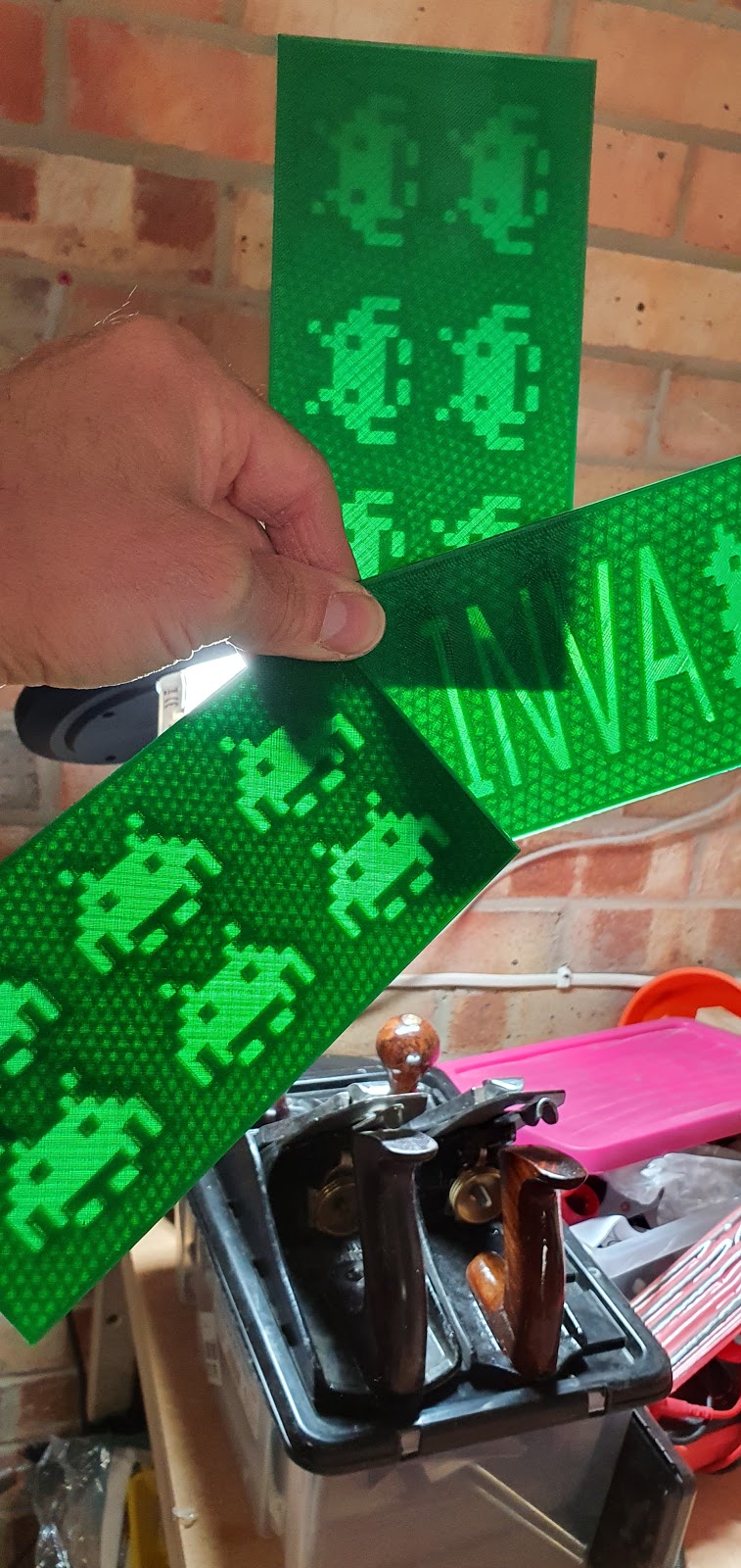
The following took place on the 29th of April. What you see here is my attempt at filling the marquee hole. On the previous tabletop cab I had backlit, 3d printed, translucent green panels with the silhouette of space invaders and the cabs name lit up in sickly green monotone. It was pretty cool, to be honest. But this machine was on a budget. I did have some cheapo, USB powered LED lights, but I had nothing to put in front of them.
So I decided to go old school and carve it from wood.

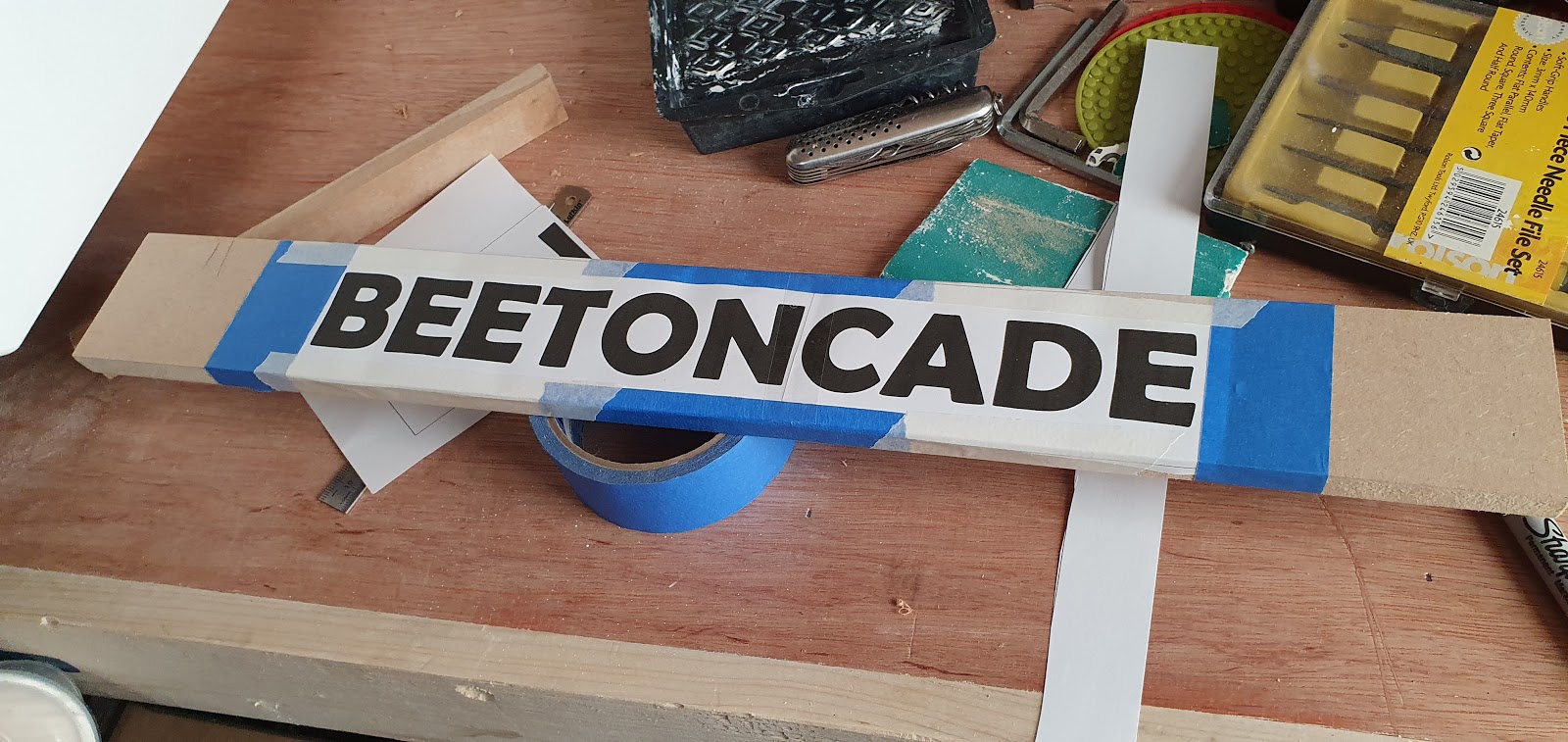
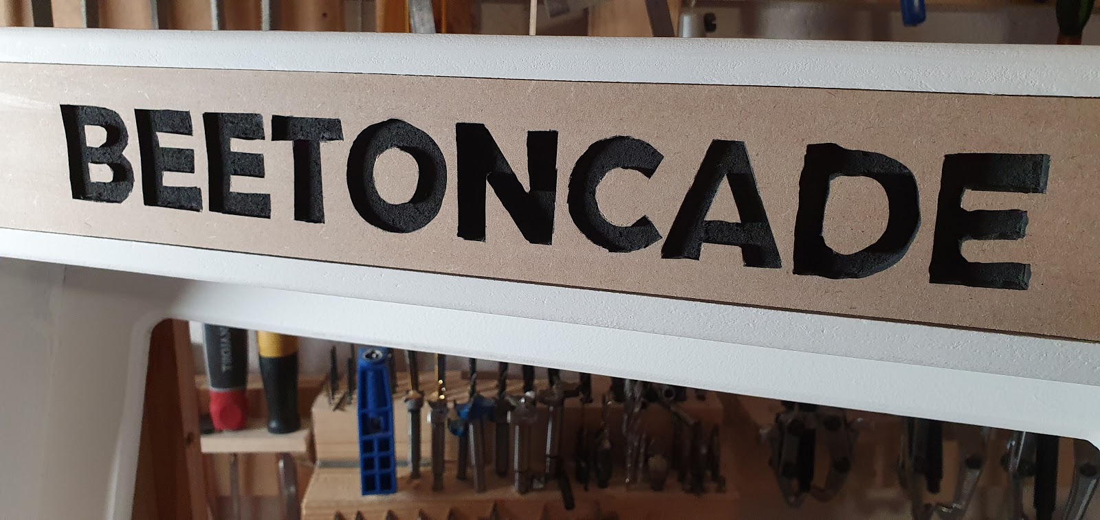
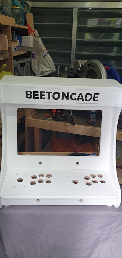
A name. It’s my nephew’s name to be accurate. A portmanteau of their name and Arcade to be pedantic. I printed it out at the correct size and taped it to the marquee panel. I intended to just carve the letters away.
I have a nice little palm router that I have customised with a larger perspex bottom plate. I can drop this into a special tabletop I have and use it as a router bench. It’s perfect for this sort of work.

My face. After seeing what the router did to the paper and MDF beneath. Not what I hoped for.

The paper was starting to catch fire. I needed another plan.

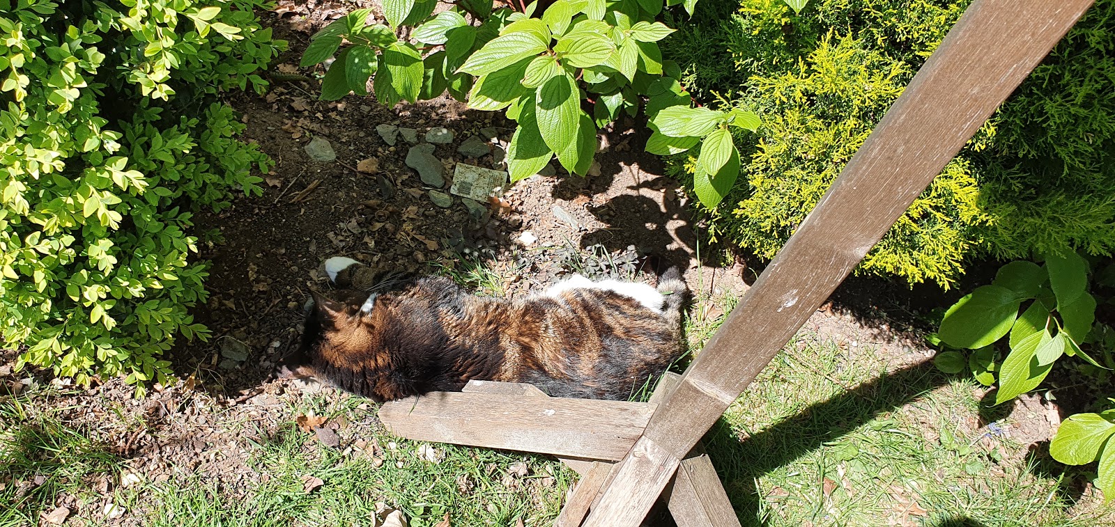
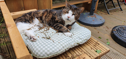
This is not a dead cat. He is just really old. He is also a woody woo.
Don’t ask.
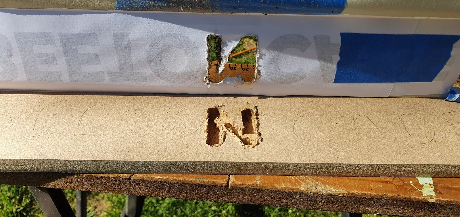
Plan two… was to glue the paper down, therefore making it more part of the wood below. This didn’t work either. More fire. More nasty lines. Part of the problem was I was trying to remove too much wood at once. I didn’t want to have to go over it again and again as I thought that would increase the chance of a slip and having to repair or start over. I ended up scoring with a sharp knife through the paper, removing the paper, then going over those lines with a thick pencil. This worked better.

It still looked terrible. I cleaned it all up with some very sharp chisels.
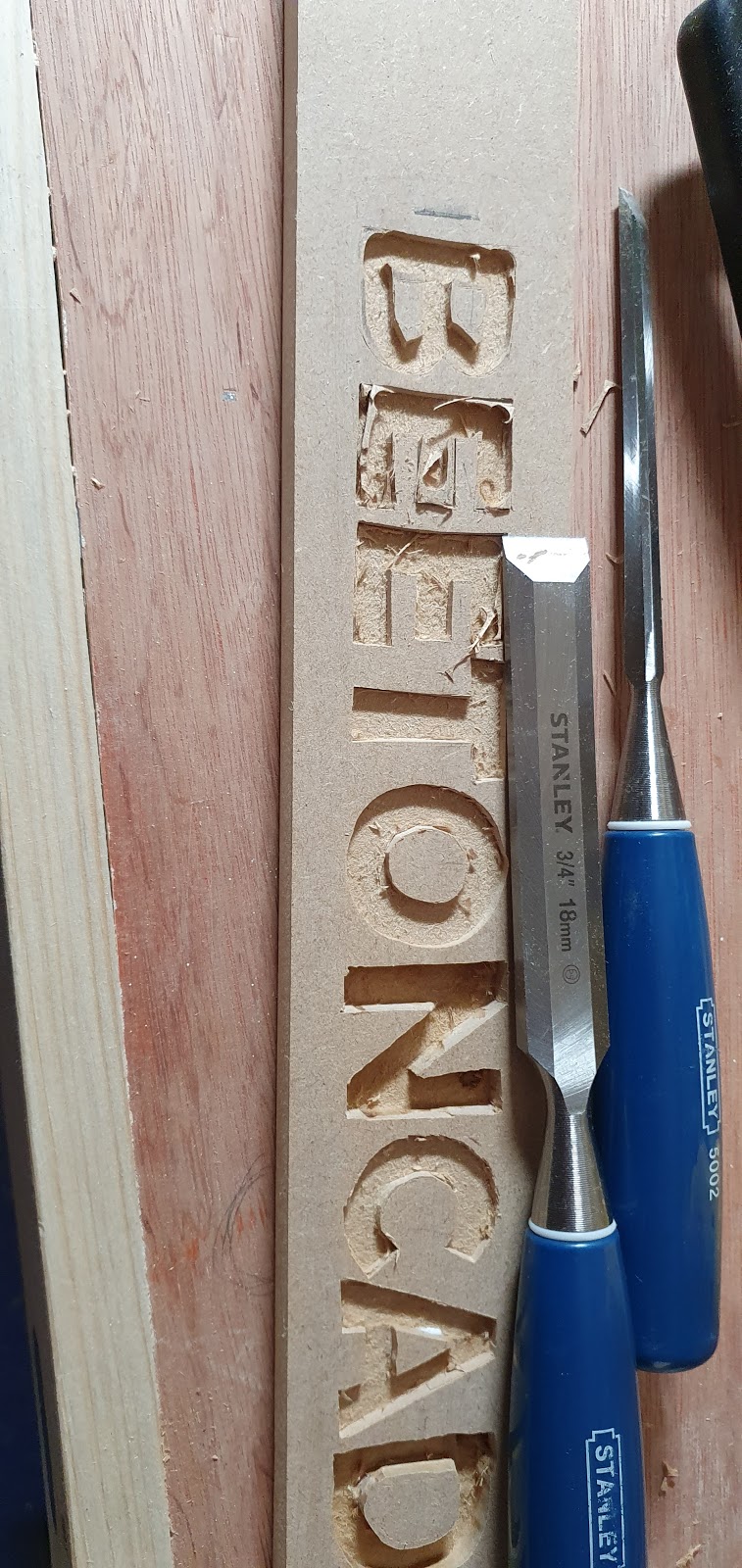
As I have already said, MDF is superb to work with. Really easy to carve.


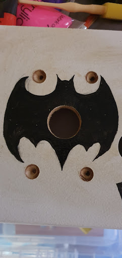
With the letters looking decent I filled them in with black paint.

Went over the lines a little! A pass over with a sanding block…

And it was done! Well, not painted, but ready to finish and install.

This is another moment when you take a look at something coming together. From a pile of chunks of wood to something that actually starts to look pretty cool. A friend remarked that the cab looked good but that the drill bit choosing game it was playing didn’t look very realistic.
And that was the end of that day!
What’s that? Still no explanation about the big mistake? Shall we see what the next day brings?
Friday, 8 May 2020
MAKING MISTAKES IS FUN! (its not, it sucks balls)
April 20th. The day I realised what I had done.
It started out like any other day. I was digging around in my garage/workshop/vr gaming mancave, when I came across a box of old, discarded 3d prints. These are test prints for the last arcade machine. The invader shape printed in black PLA at the top of this pic is for two front panel buttons. The crazy shape in green at the bottom is a template for cutting out that shape in MDF for mounting the button and joystick housing I 3d printed for the last arcade cab. Count the button holes… Remember that number.

That last cab had these parts in the marquee with LED lights behind. It looked really cool. The only problem is PLA is not the best or most reliable material. And it turns out putting hot little LED lights right behind it in an enclosed space makes it heat up! And PLA has a very low melting point. Yes. The last marquee drooped a bit. It’s an age thing.
A set of LED lights from that reputable company… er… I have never got round to using these in anything. For those not aware of the English colloquialism, the dictionary definition is “an unattractive or unpleasant person or thing.”

These were what I had been hunting through storage for. These controls were from my very first attempt at an arcade cab.

It pains me to share this, but this was my first. She’s an ugly thing but she gave me hours of pleasure. My biggest mistake (apart from that MASSIVE bezel, the huge chin on the control panel, the multitude of controls on the frankepanel, and the fact it weighed as much as a small car) was I got it to this stage and then started playing games on it. That killed the project dead, never got any further. Half of the controls made their way into the last bartop I built, and half into BEETONCADE.
Oh look! Seven buttons!

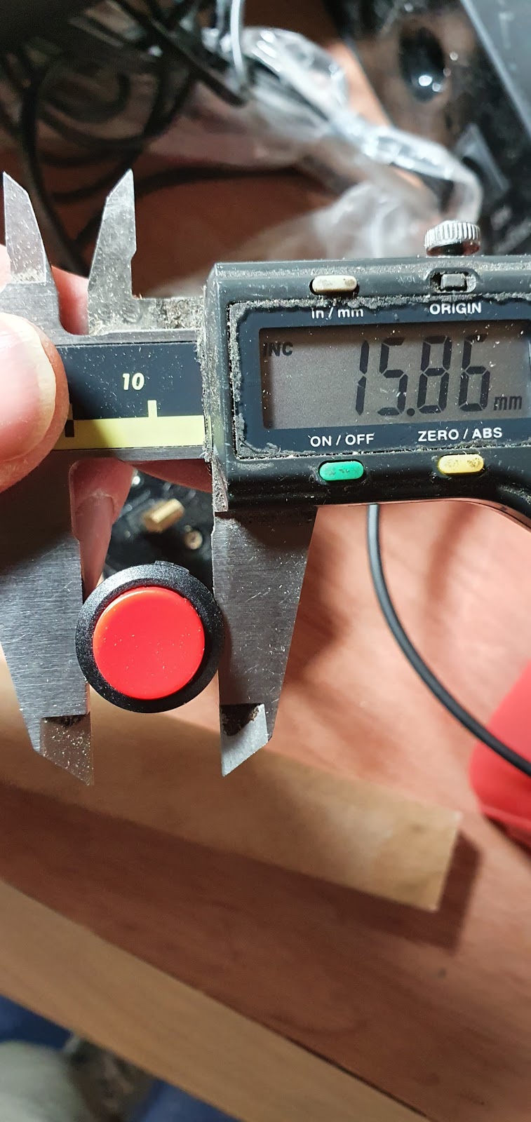
I had a count up. The number of holes I had drilled meant I only had enough buttons for each player (eight each) if I used some smaller buttons for start and select. Also, one of the buttons was missing a few important features, like its inside bits.
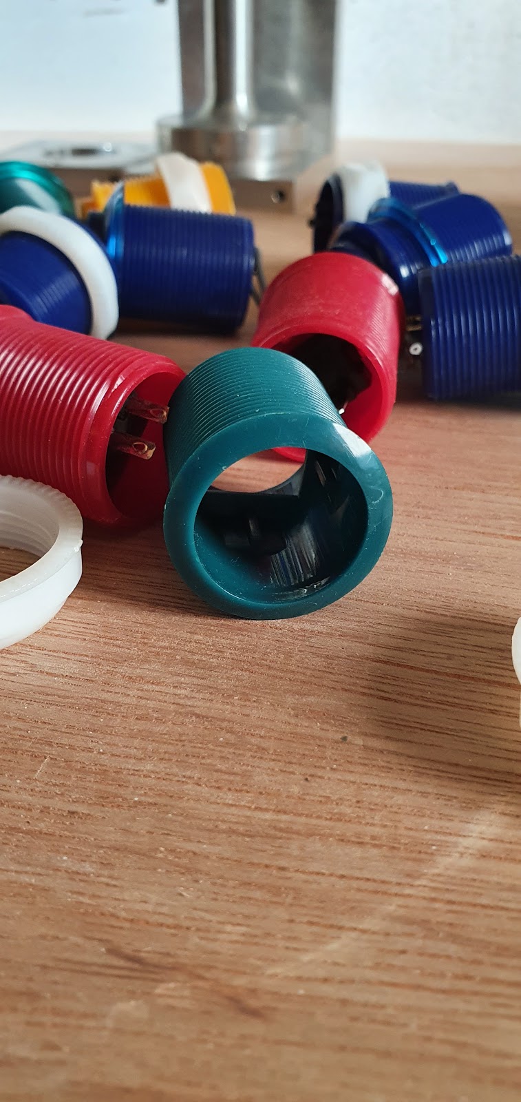
Here are the buttons I decided to use for the start and select controls. They are nice and small, they don’t need to be clicky as they don’t serve a purpose during gameplay. Perfect. Everything was going really well at this point!

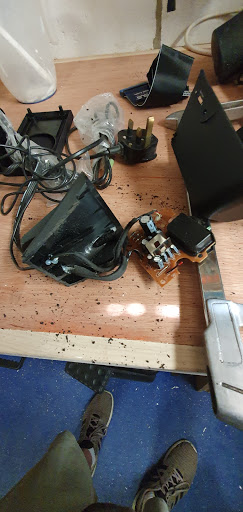
I had to commandeer these speakers from in the house. They were being used as a white noise generator to aid sleep for one of my family. They get plenty of sleep, and I needed speakers.
Actually, I bought them a new pair and took these ones. The new pair would probably have been better as they had better inline controls. That would have made mounting the volume controls easier. But these actually sound pretty good for an old set.

The secret to getting the front off is, be nasty.

Couple of screws under the front panel and we can see the inside bits. Nice tiny speaker, should be a doddle to mount inside even this tiny arcade cab.
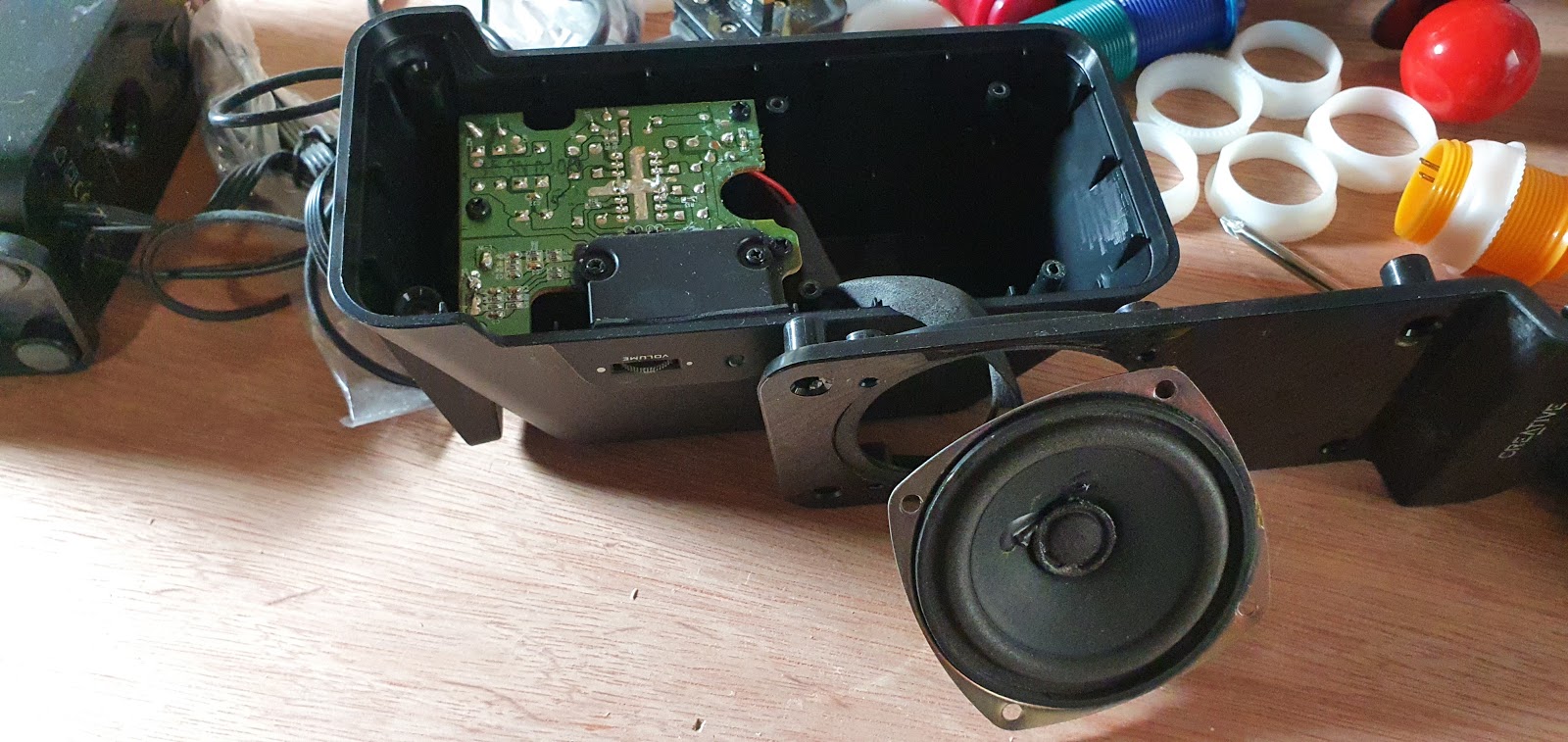
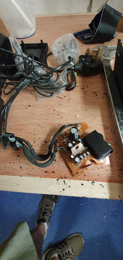
This is the volume controls and amp. It ended up being very fragile and required a lot of fixing to make it stable.

Trying out various options on mounting location. Bottom of the case was not going to work, I had a lot of stuff to cram into that tiny space and speakers that fire down under the unit don’t work quite as well. The marquee was the way to go, I would have liked to have them firing straight out through the marquee front, there is room either side of the name, but the speakers are just a little too large and cutting them down would be risky. Firing down from under the marquee turned out really good.

Thought it would be a good idea to test out the buttons, make sure none of the ones with a full complement of inside parts were dud. All of them, not the empty one, were fine.
And a test fit in the control panel. Nothing fixed yet. Wow, that’s a lot of buttons…
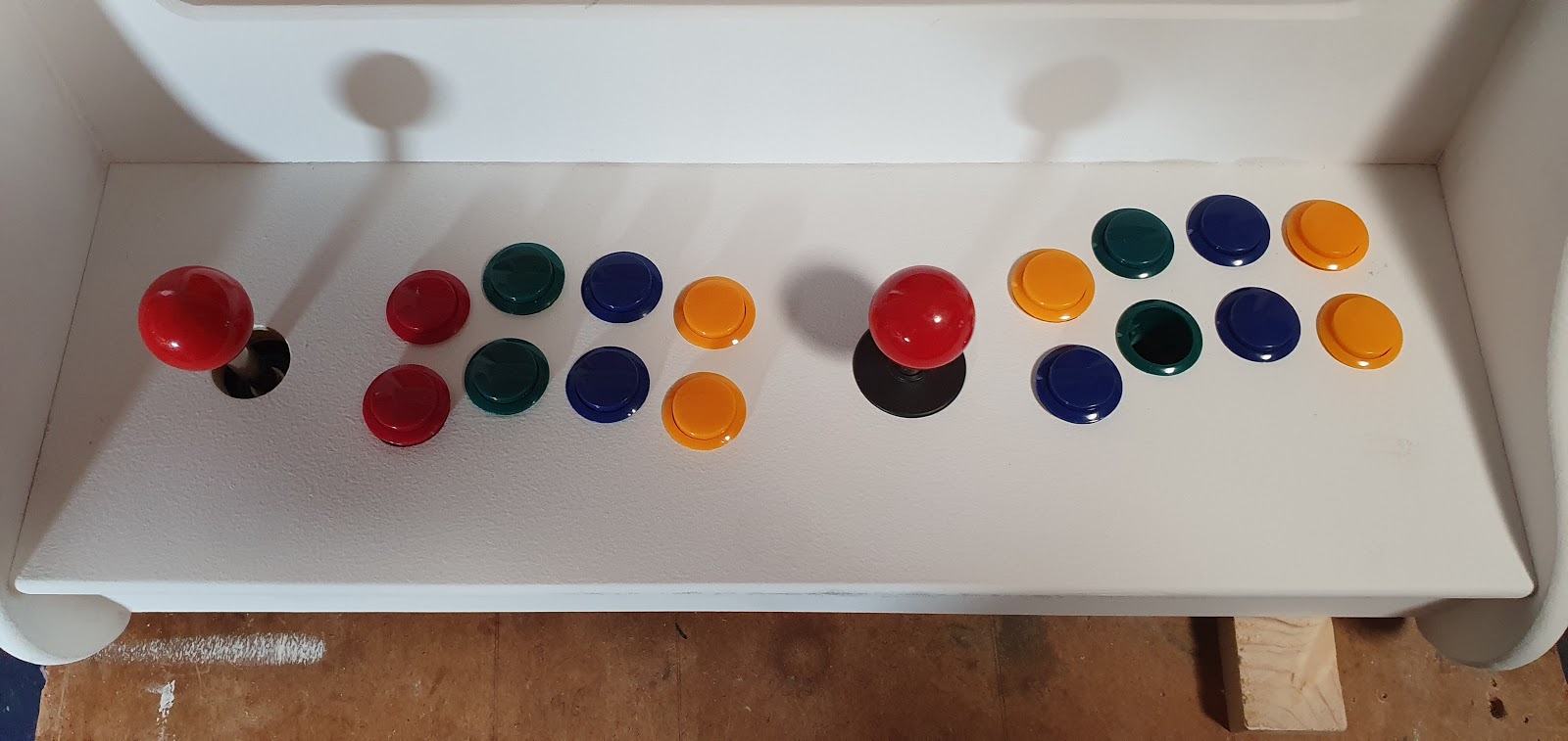
Anyway, never mind that, here they are from beneath! Feel like I am making really good progress now!

Going to need 16mm holes (sorry imperials) for these other panel buttons.
Screws found in the screw nest for the joysticks. I usually mount from beneath by screwing into the wood, but MDF is not very strong when used this way. It will work, but it wont like being taken apart multiple times. There will be two nuts for each bolt to stop them working loose.

In a big hurry now, no idea why, think my subconscious was trying to point something important out to me, some important detail I was missing. Never mind all that, on with drilling holes in stuff!

Lined up the joysticks under the control panel and marked out the screw holes. I freehand drilled these as, because idiot, I had glued the control panel in place. Bit tricky getting it to balance on the drill press!

Here are fresh holes.

Countersunk, or started to. You can see the screw isn’t sitting flush or straight. The holes were crooked.

A stick is attached. Lotta holes under there. Looks like swiss cheese.

Again, you can see the screws are not straight. Annoyed at this.I compensated by making the countersinks slightly deeper. Terrible.
And then it hit me. Why did I have eight buttons per player? I was intending, in order to keep costs down, to use the GPIO connector on the pi to connect the controls. Now the important detail here is that the GPIO connector will support a joystick and eight buttons per player… INCLUDING start and select. So, six player buttons per player. I had a sit down and cried for a bit.
Choices.
I could swing for a couple of zero delay USB encoders, I even had one hanging about, but that wasn’t exactly spare. I would still also need to replace the button without buttony bits inside if I did this.
Or…
I could rip the control panel out and make a new one. This carried risk but was the cheapest and neatest option. The risk was I would tear out important bits of wood when I took the control panel out. Wood glue is AMAZING. It doesn’t fail. The wood around it fails. So when I pull it out, either the wood on the control panel gives, or the wood in the cabinet does.
Removed any screws that were joining it to the cabinet. Could actually safely remove all the screws in the cab now, they are only there to hold the wood in place while the glue dries. I took a large piece of wood, and a hammer, and started whaling against the lip under the front edge of the control panel.
The control panel gave up first! Result. It left some DNA in that bottom edge but that would sand off easy later. And that was the end of that day…
April 21st. A new day. No more mistakes! Nope, not me. Going to be plain sailing from here on out.
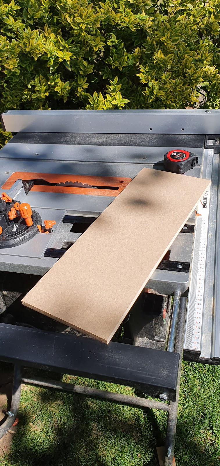
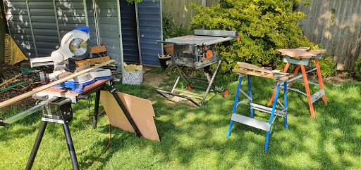
First job, new control panel. Got a new table saw! It made this so freakin easy. Wish I’d had it for the other parts.

Rounded over the front edge. A little rounder on the top than the bottom.

It’s a perfect fit. You can make this cut, this accurately, without a table saw, but it would take a lot longer. Certain tools are there just to save you time. Also for repeatability.

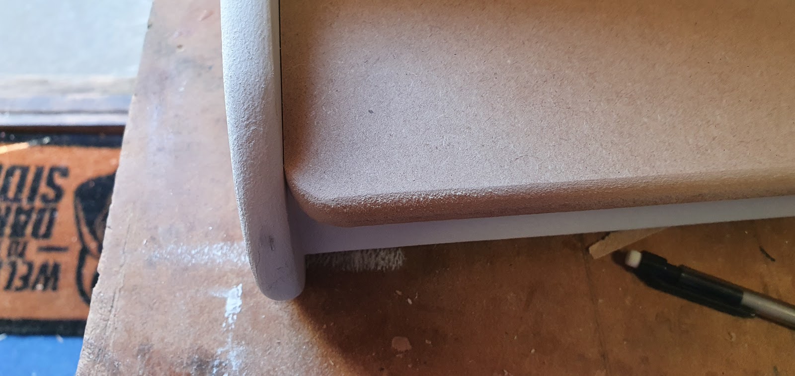
I had made this control panel slightly deeper, when testing the old one for fit I found there wasn’t enough wrist rest to be comfortable. So I extended it out beyond the side panel. It left this ugly corner that needed changing.

A paint can to draw a curve and five minutes with a palm sander.

Much better.
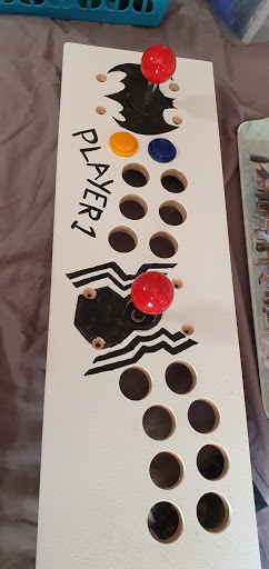
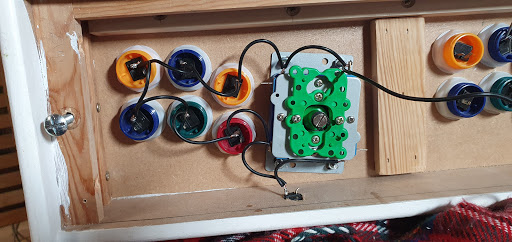
Now I work out where I want the controls. This time I made them a little further apart (had some room as missing four buttons!) and rotated them away from each other a little more. Gives each player a lot more elbow room. Using the plate from the bottom of the joystick to line things up.
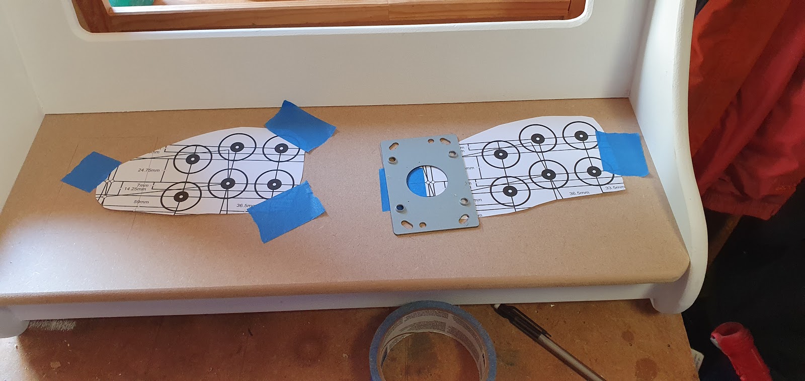
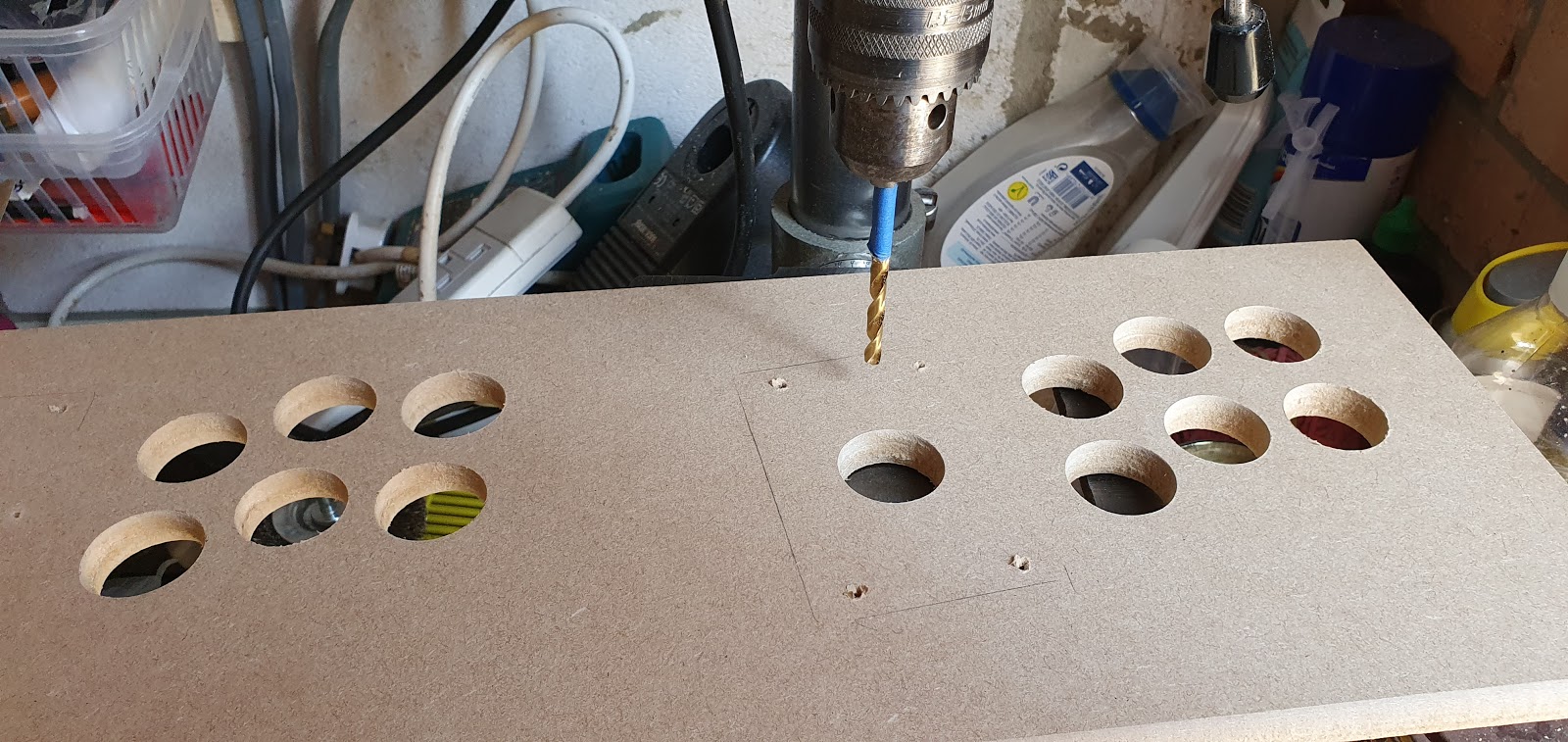
Without some idiot glueing it in place it was easier to use the drill press to drill nice neat, straight holes.


Back out into the fresh air with spade bit for the 28mm holes. Hate this bit. Need a better mask, but for some reason they are kinda hard to get hold of right now.
Took my time, going from side to side.
Probably a little over-cautious.
And we are through. Didn’t take too long this time.

Another test fit to finalise the joystick position. There’s an outline on player two’s side.

Back to the drill press. These are the important holes.
I used the drill press with the countersink bit and it ended up being much nicer than the previous attempt. It’s almost like I knew that last control panel was going to be junked and made a hash of it on purpose.

While I had the drills out I marked the positions of the start and select buttons. Start buttons on the bezel below the screen, out of the way of accidental presses, and select/add coin buttons below the control panel. I put them there to ape how you would reach down to slot in another 20p when playing Golden Axe. Yeah, it was 20p when I played it. Also, ape.
Test fit of the small buttons. They are meant for thinner panels and are push fittings, they would need hot glue to stop small boys working them loose.

Added a brace at the back of the control panel. 12mm MDF is a little bouncy. This helps.

All the holes!

And another goosebump moment. Even though I had repeated a lot of work while replacing that control panel I felt pretty good when I took that pic.
Couple more things before I gave up for the day. Added a block of wood here. I intended to put the pi here but in the end, I didn’t. But it was fun using my nail gun to pin it in place.

And final job of the day, a coat of acrylic primer on the marquee and the new control panel.


That was a LONG one! Prizes if you got all the way through. Send me a coded tweet that has the word “haddock” in it somewhere and so I know who the real heroes are. Yeah, you are the real heroes my secret haddocks!
Coming next! – Speaker mounting, wiring and grilling.
Saturday, 9 May 2020
SPEAKER SURGERY!
Welcome back! Only one person got the haddock so far. If you don’t know what I am talking about then you haven’t been paying attention!
This post I am going over April 22nd’s progress.
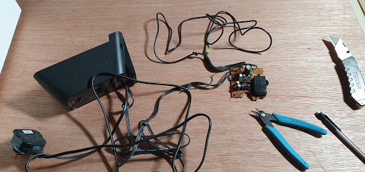
Decided to get a grip on the speakers. To move forward I needed to know exactly what was going into the bottom of the case and the only unknown variable was the speaker’s guts. So I needed to spill those guts!
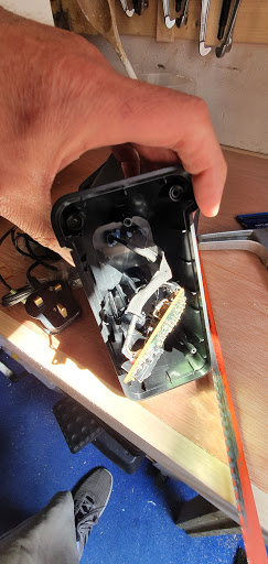
Precision hacksawing. Nothing could possibly go wrong.
Trying to free the control/volume board from the plastic housing. Cutting plastic with a hacksaw is messy. Ignore the skinny legs, they cannot be real.
And it’s free! Perfect.
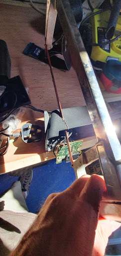
Perfectish? I didn’t realise that hidden inside the plastic housing was a knot of the cable I was trying to free. Turned out this was the line in cable and I would be shortening it a lot anyway. No problem.
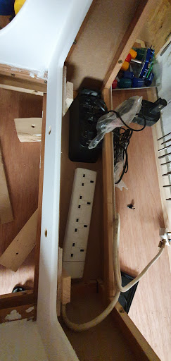
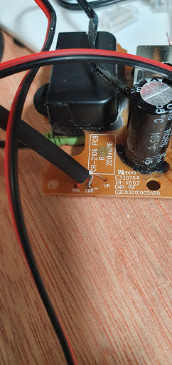
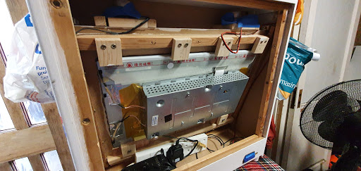
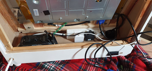
This speaker contains the power supply. Instead of building a housing for it I decided to keep it in this casing and screw it to the base of the cabinet face down.
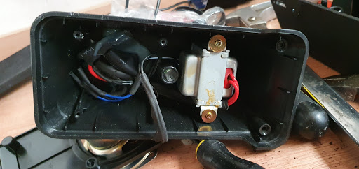
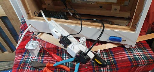
Kind of like this. Dropped a four-way power strip in there to get a feel of the space I would have. It ended up a lot less than this!
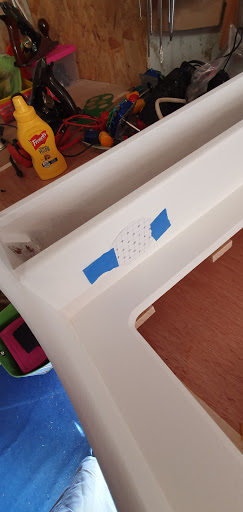
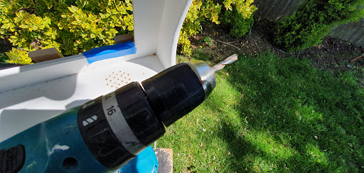
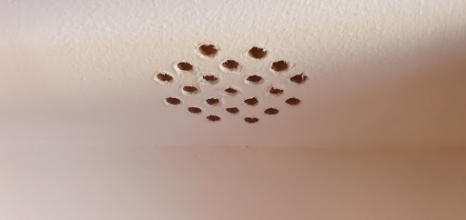
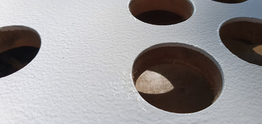
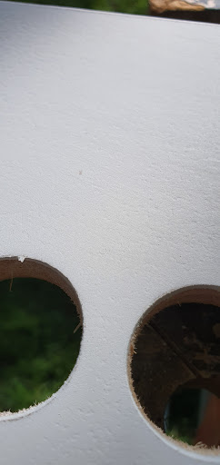
Cut out a grid of dots in a roughly circular pattern. Taped it to where I wanted the speakers to be mounted and grabbed a drill. In wonderful hindsight this would be a hell of a lot easier on a drill press. A lot neater too.
Tiny pilot holes first.
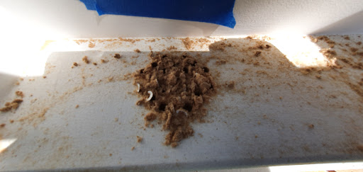
Then a little bigger.
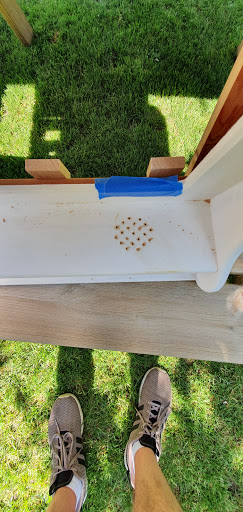
Then the only drill I had that was the right size for the final hole was this pilot drill from a hole saw set. It had a really aggressive rake on the cutting edge and made a massive mess of the holes.
I ploughed on regardless. It isn’t a visible feature so I was not worried. And I planned to cover it with a 3d printed speaker grill if it was a total disaster.
Looks like 3d printing speaker grills was in my future!
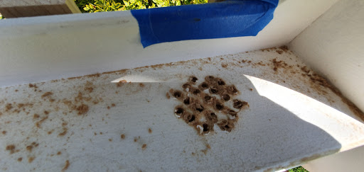
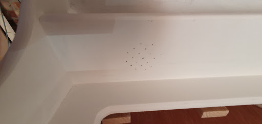
Cleaned up and sanded flat it looked better.
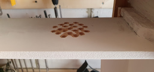
And then, with a coat of paint, I was happy to leave it like this. This is one of those things I would have spent more time or money on if either was something I had more of.
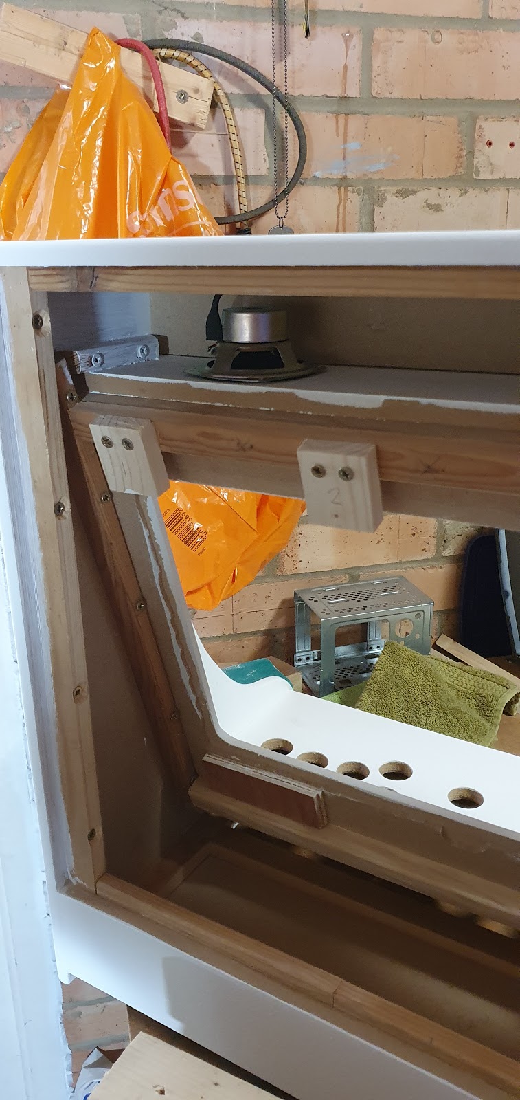
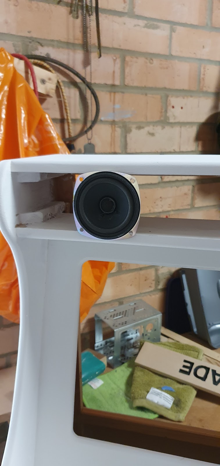
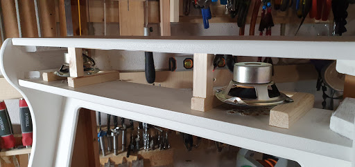
Cut some battens for the speakers to sit on. The drivers need space to work, if they are screwed flat to the wood they cant move and would not sound good.
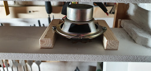
Stereo!
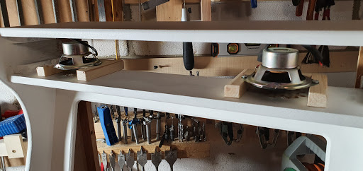
Added a small block to hold them down for when I came to glue them in place. Note I had painted the inside of the marquee white. This was in case I ended up going with a backlit, transparent marquee. Would make the lighting brighter and more even.
And that’s all for that day.
Coming up! Jigsawing, hacksawing, drilling, and a mystery nail!
Saturday, 9 May 2020
TO DO: FLOORS AND DOORS.
April 23rd.
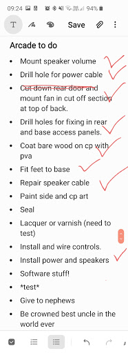
I was now mostly recovered after the eight-hole-per-player fiasco. So, to give myself some much-needed motivation I made a list. This actually worked! It is something I intend to do more on future projects.
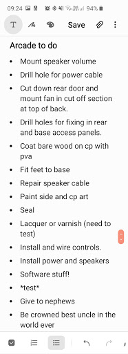
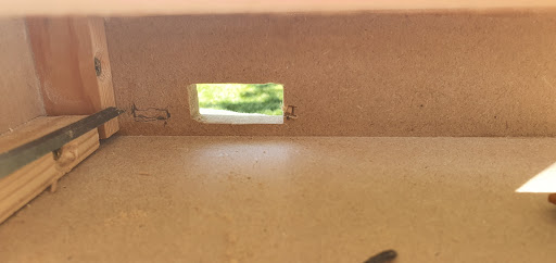
Having learned from the last bartop that heat can build up in a sealed-off wooden box full of hot electronics I decided, especially as this was going to family members, to make this one less burnie. This USB powered fan was meant for a Vive Pro wireless headset adapter. Never needed it in the end so decided to use it here. Only a tiny fan but all I needed was to encourage some airflow in the right place. This wasn’t planned from the start so I hadn’t cut a hole anywhere for the fan.
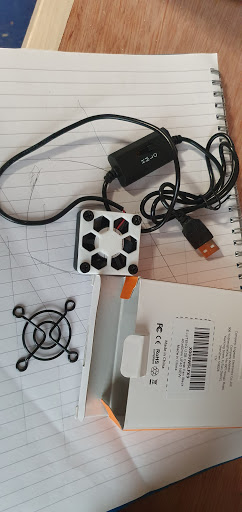
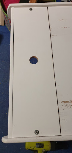
Except for this one! This is the finger hole for removing the back door. It is exactly the right size. I was thinking of cutting a chunk off the top of the door and fixing it in place permanently, in the end, I just left it the same size and mounted the fan in this finger hole.
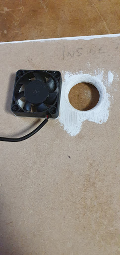
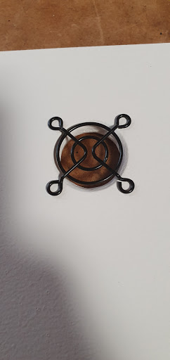
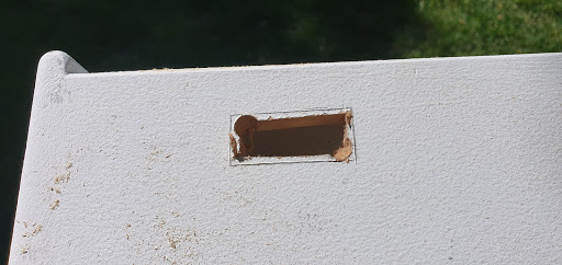
The outside would need this cover to stop small fingers getting trimmed.
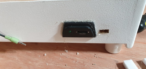
With that decided I went back to making a mess. I needed to mount the speaker volume control somewhere. The only available place was the back near the base. Marked it with a sharp knife to prevent nasty tearing.
Drilled a couple of holes for the jigsaw blade to start from.
Cut most of it out.
On the inside had to take a small chunk out of the right side of the hole to allow part of the circuit board to fit.
To the left of the hole I had to cut all the way through. There was a chunk of board that protruded almost the whole way. I could have tried to get this to be just below the surface, but that would have been a weak point. Plus, its the back of the machine, I was in a hurry.
So out it came. A less than perfect fit, but hot glue was going to seal any gaps.
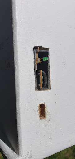
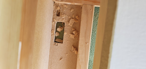
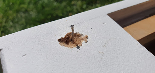
This hole contains the mystery nail. Needed a hole for the power lead. Again, with more money and time I would have mounted a kettle lead socket and an external, fused switch. But a flying lead was all I could do here. So this hole was where it was going. Sparks don’t usually fly when you drill MDF.
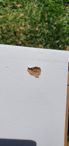
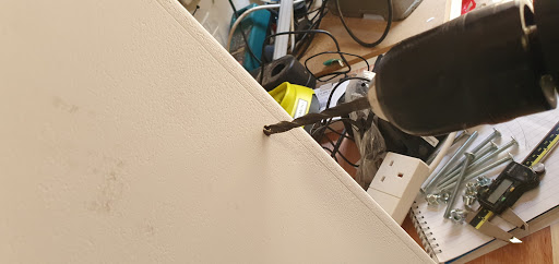
A little digging and one of the brad nails was evicted.
Hole drilled and countersunk to prevent hard edges cutting into the cable over time.
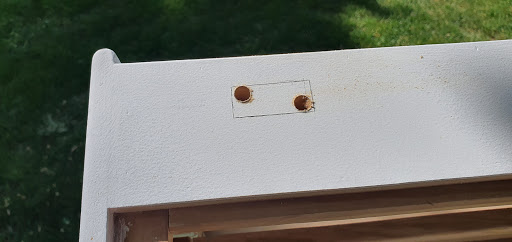
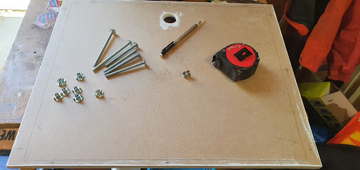
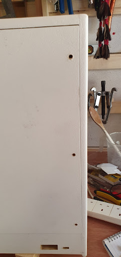
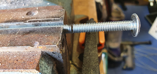
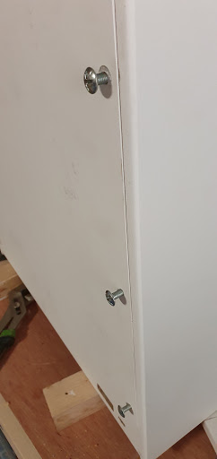
Marked out the holes for coach bolts and t-nuts to hold the back door in place. I had originally marked out three along each edge. Then I counted how many bolts I had in stock (hardware shops closed at this point) and decided six would be plenty.
Door in place. It fits very snugly.
With the door in situ, I drilled through with the same drill and then took the door out and made the t-nut holes the right size.
All my coach bolts are too long. A few sweaty minutes with a hacksaw sorted that. Rounded off the ends of the bolts with a file.
Pleased with my work. Something else to cross off that list.
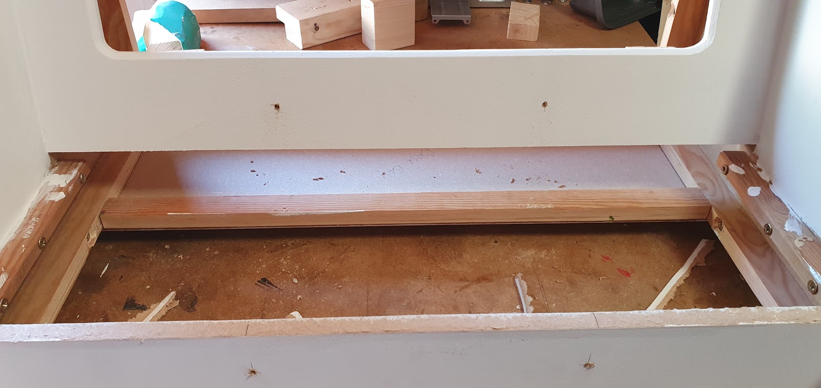
And the base door got the same treatment. Note this also has a finger hole. This one will not be housing a fan but will be handy as an inlet for cool air.
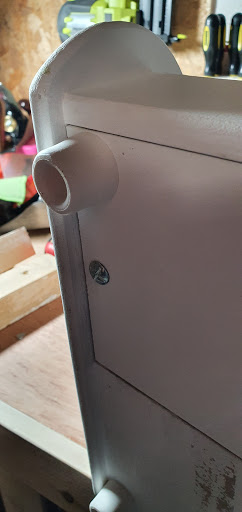
Whilst I had it upside down I screwed some door stops to the base for feet. Used these before and they are perfect.
Last job of the day, PVA the bare wood. Probably overkill but if this ever gets splashed in a puddle of something disgusting then it shouldn’t swell up too badly.
And that was that day done and dusted. The list was crushed, smashed it out the park. I remember feeling pretty good about life at the end of that day. Smug face.
Pretty much all the easy stuff left to do. Should knock it out in a couple of days. What a naive idiot.
Sunday, 10 May 2020
A MIXED BAG OF JOBS
Welcome back! Or, just welcome!
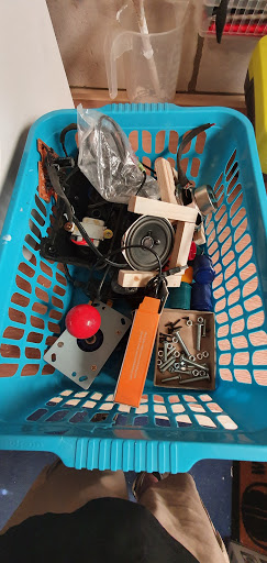
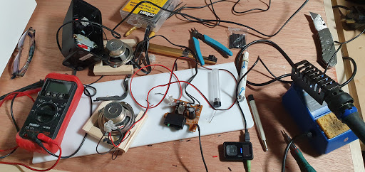
Today’s post is about the work done on the 24th of April. We start with a mixed bag. Actually a basket. I tend to be working on multiple DIY jobs, and small projects, all at the same time. Really helps to keep parts for each in separate containers. All of this lot needs to be mounted in the cabinet at some point.
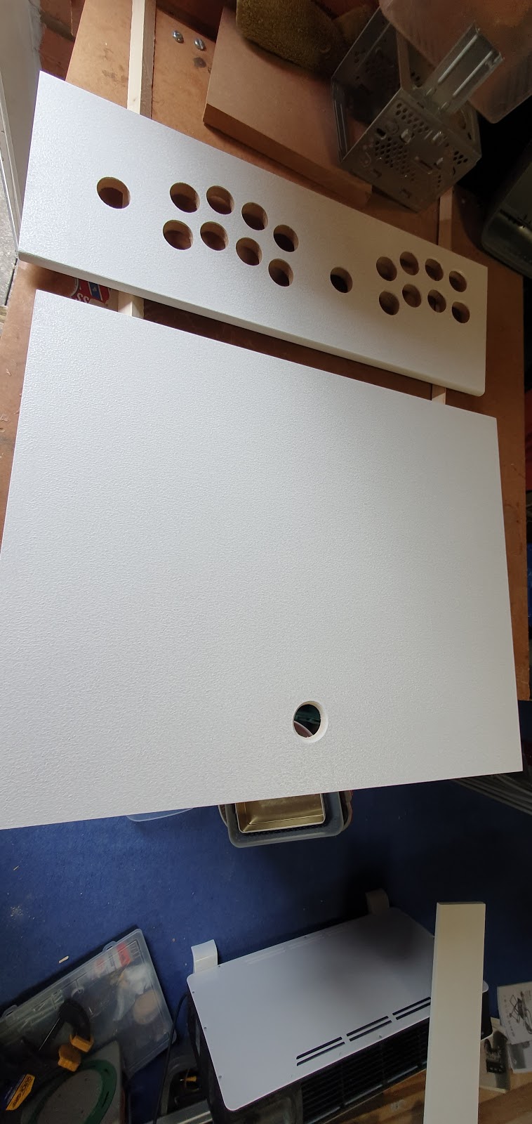
A closeup of the control panel paint finish. At this stage, it has had three coats of acrylic primer and the orange peel is strong. Its not a terrible finish to have, but I did intend to paint directly onto the control panel – something that got scrapped towards the end. So this would need sanding.
After sanding most of the texture has gone. Could probably go all the way down to completely flat but I was under time pressure, this would do. The final coat would be an acrylic lacquer, but that would have to wait until the art was on.
Fed up with dust and sanding I decided to fix the speaker and get the cables sorted.
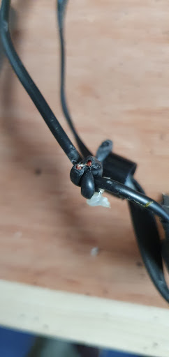
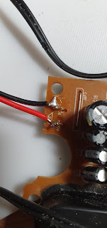
The line in cable had been partially cut through when I hacked off the plastic casing. The cable is way too long, and the ends are easily accessed on the board so I decided to cut it to length and solder the cable on the board.
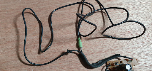
Cut to length with some heat shrink ready. Been a while since I soldered, and this went fairly badly. Had to repair a few mistakes, and discovered a broken joint on the board which I repaired.
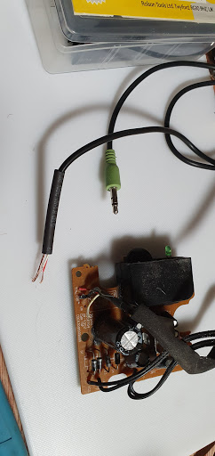
Little MP3 player at the bottom for testing, no way I would plug my phone into something I had repaired! Works fine.
I used to be able to solder to the legs on a chip on a PS2. Probably best not to ask why. Not so neat these days but it seems to work.
Splattered all the fragile parts in hot glue to protect them from ham fists during installation.
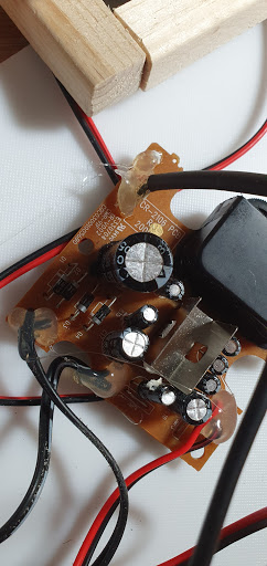
And there it is installed. Screwed the power housing down using its original screws. It is very secure in there.
And finally hot glued the volume control in place. Hot glue is messy. Its the back. *shrug*
After this day’s work I took a few days to have a breather, had been working really hard on this. But now I knew all that was stopping me putting all its insides in was finishing the paint job. That would mean CUSTOM PAINTING! Art was about to get real.
Sunday, 10 May 2020
ARTISTIC SENSE IS TINGLING!
I got lazy for a few days. Well, it was the weekend and I had been working really hard on this for some time. The break did me good.
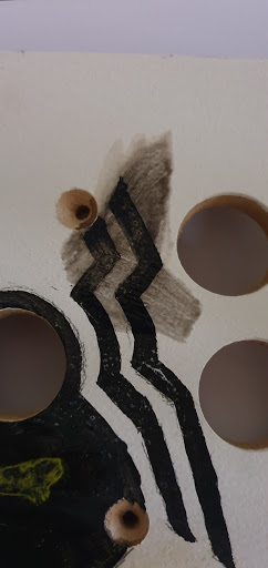
One other reason I was making little progress was the need to get the art on the side of the cabinet. For this, I needed a projector. I can draw but I am pretty slow and personally think my skill is average at best. I freehanded a batman and spiderman logo onto the discarded control panel, this was for a few reasons. I needed to see what the paint looked like on the primer base coat. Black turned out good, I probably should have tested other colours. I also needed something to test a finish on. I needed a good clear coat that would not smear the painting, these logos would later be used for testing that. I don’t have a suitable projector so needed to borrow one, that couldn’t be done quickly under lockdown so I had time to kill.
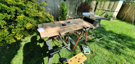
While I waited for loaned projectors I decided to replace my workshop door. I bought this hardwood front door a few days before lockdown for £10 on facebook. Needed holes filling as the lock and hinges were all in the wrong place. First time hanging a door. Seems to have worked quite well!
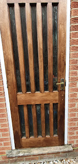
Did leave my workspace in a state though.
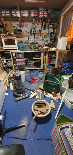
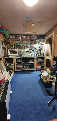
So satisfying getting it all back in order. By the way, the Union Jack flags came with those boxes. I’m a proud brit, but I’m not a raving gammon.
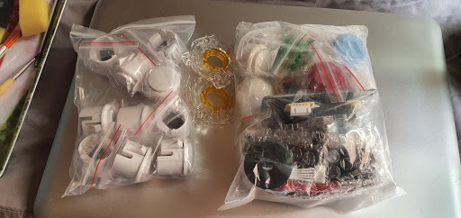
Post arrived with a nice surprise. Ordered these a while back from Amazon warehouse for very cheap. A load of white buttons on the left and a complete set of controls on the right, including a zero delay encoder. Something for a future project. (Follow me on twitter @ZZleeZZ if you want to get daily, and sometimes blow by blow, updates.
More playing with projectors. I was still toying with the idea of art on the control panel. I decided not to in the end.
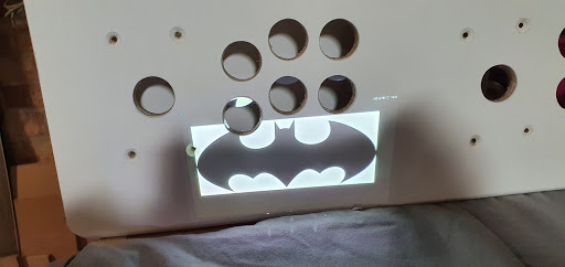
First look at something projected onto the side. The projector is actually a Lenovo android tablet with a built-in pico projector. It’s actually brilliant and I would love to own one. I also tried out an old NEC projector of the more traditional type but could not get a focussed image the right size.
Final positioning, I would have liked less cropping but needed to keep things reasonably big to aid my failing eyes while painting.
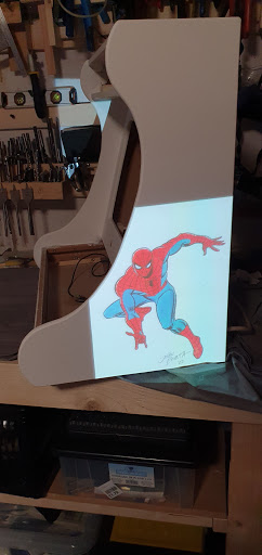
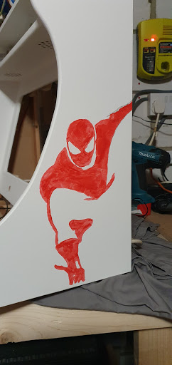
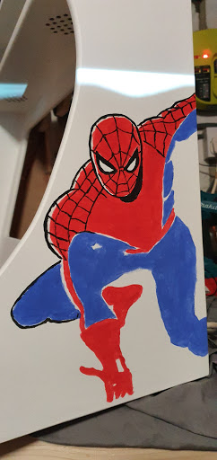
I thought the best way to do this is the same way it’s done (to the best of my limited knowledge) in comics. Colour goes on first (over the pencil sketch) and the black lines after.
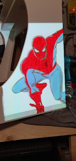
And this is the crushing disappointment pic. I blocked off the projector (scared to turn it off in case it moved the image) and saw this tomato ketchup splatter on the case. I came very close to giving up. It was already late, I was tired, I couldn’t see this ever being good enough. For some reason, probably tired bloody-mindedness, I decided to just finish it anyway. I’d probably paint over it in the morning and give it to them plain white.
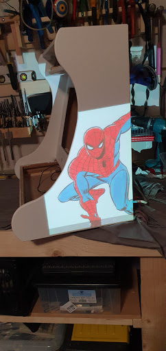
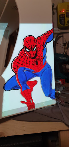
And so I carried on. The blue was added…
And now I felt less bad. It was still terrible to look at, but at least it didn’t look like the pavement outside a nightclub at 3am.
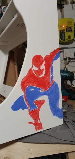
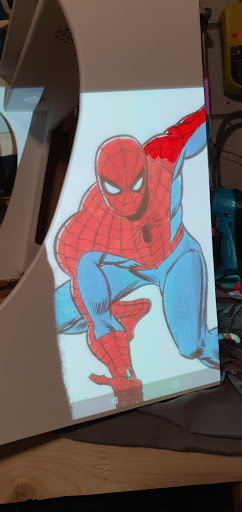
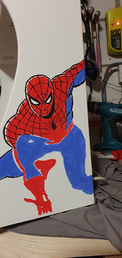
WAIT! What the actual..? What happened?! Reinvigorated I ploughed on.
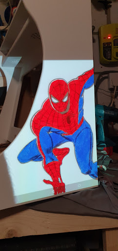
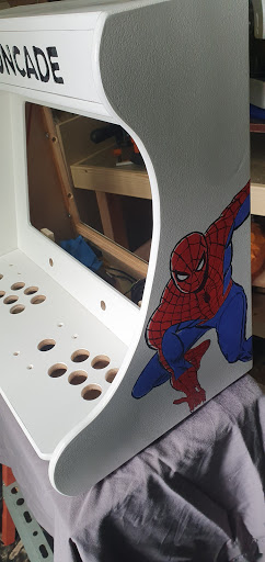
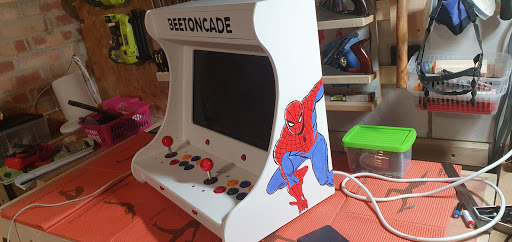
And little by little I worked at it. I never want to paint that webbing ever again ever!
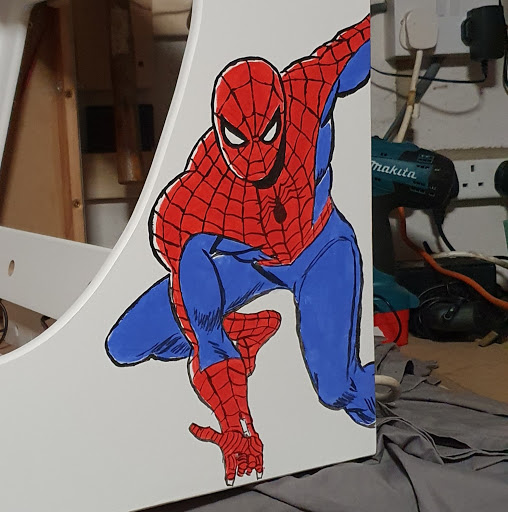
And with the projector blocked.
And done! It took me four hours to do. Which is actually not bad if you think about it. I went to bed that night, late, with a massive grin on my face that stopped me sleeping for a long time. Stupid grin. I was BUZZING. And, for some stupid reason, I kept thinking that the Batman side would be easy! IDIOT!
Monday, 11 May 2020
NA NA, NA NA, NA NA, NA NA. NA NA, NA NA, NA NA, NA NA. SIDE ART!
28th April.
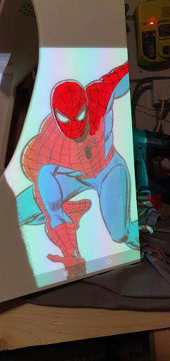
Before I started on the other side I thought I should test some finishes. I had a feeling I would be spraying it with acrylic lacquer but wanted to see, for future projects, what other finishes would do to the paint.This first one looks ok from a distance and in bad lighting. It’s an oil-based varnish. It doesn’t smear the paint and I’m sure will leave a good protective coat. The only problem is it looks like a tramp urinated on it – on a hot day after a really long walk in the sun.
Second attempt. Oh dear. This didn’t go well. This is brushed on acrylic varnish. It mixes right in with the paint. Nope! I did try sealing the paint layer first (sorry no pic) in another test. I used a cheap aerosol hairspray, this actually worked reasonably well and prevented 90% of the smearing. Still not good enough. I did seal all the cabinet artwork with this hair spray before I sprayed it with acrylic lacquer.
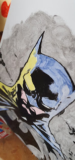
I’M BATMAN.I had intended to use a batman from the animated cartoon. It would have been a lot easier, with no blending and fewer colours too. At the last minute, I came across this one. Once I saw it projected on the cabinet I knew I was going to have to try to paint it. After the success of the Spidey side I was full of confidence. What could possibly go wrong?!
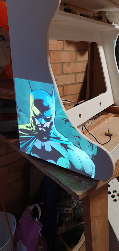
Oh bloody hell. Again, crushing disappointment. I mean LOOK AT IT?!?! Having learned from the last try I just took a deep breath and started chucking paint at it for a few hours. Unfortunately, probably because I was convinced it was going to be painted over anyway, I didn’t take many pics of the process.
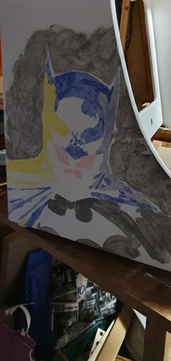
It wasn’t till I got to this stage I realised it was going to actually be ok! The black was a lot harder to do on this one than spiderman. There is a lot of detail in the shadows. I was a little stunned, to be honest.
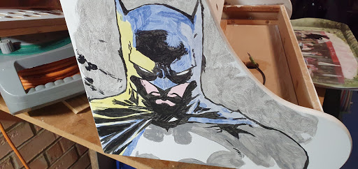
It all came together really nicely. I liked the background so much I wanted to put one on the other side behind spiderman. I relented in the end. Leave it alone as soon as you can, is a good motto.
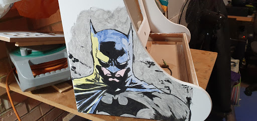
And so I did. Again, I went to bed very tired but very happy.

As I said before, I had intended to put a lot more, smaller logos etc. on the rest of the cabinet. But time was against me, also I now knew how much work that would entail. I had put at least eight hours into these two paintings. It was worth it, but painting A B X Y START SELECT really isn’t that important.
So all that is really left is all the inside gubbins and the final coat. Easy peasy?
Monday, 11 May 2020
I SEE THROUGH YOU
MAYDAY! 1st of May 2020.
After another couple of days off (arting is HARD, also it had rained a lot) it was time to get moving again. First job on the list was the clear coat. Not a lot of pics of this as it really isn’t very easy taking a photo of something transparent. A clear afternoon with a low chance of rain meant I had to spray in my shed, not ideal but it had to be done at some point, and relying on the weather in the UK is something you learn not to do.
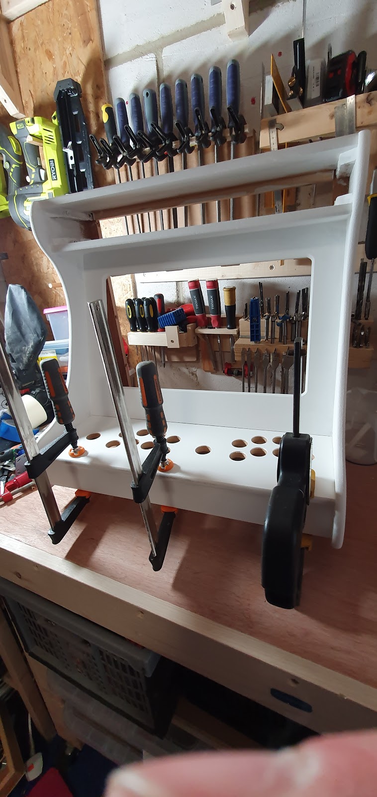
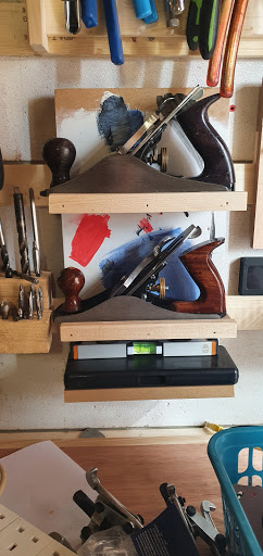
Between coats, I worked on a shelf for my hand planes (extra shelf at the bottom for my vernier and spirit level).
Nothing much to see here, which is a very good thing. If this was going to go wrong it would be most likely now. I ended up giving most of the cab three coats and the side art four coats.
No excuses now. Time to start filling this puppy up from the back… er, that came out wrong. And that is most definitely not what she said.Monitor in, along with the power strip.
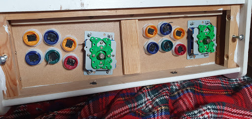
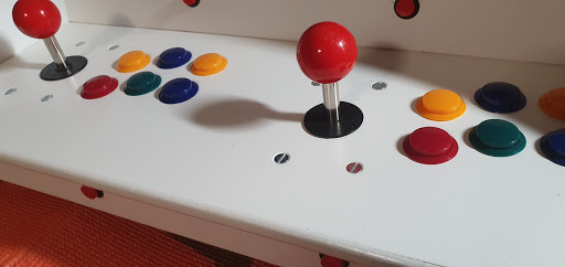
Base access gives me smug face. It is so much easier than the last cab I made. Sticks going in.
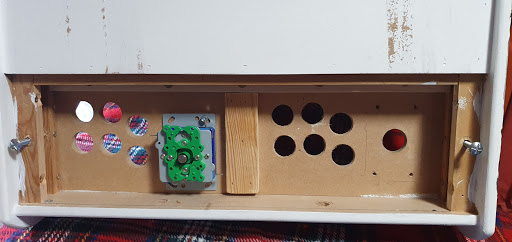
And the buttons. These took some work to get in, I ended up having to rub down the holes a little. They had been given a coat of PVA, that makes the fibres of the MDF stand up and go really hard (can’t get Steve Carrel out of my head! THAT’S WHAT SHE SAID) they needed a lot of shoving to get them in (oh for crying out loud!)
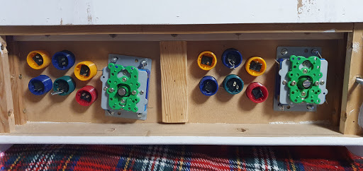
Looking sweet. Buttons are in for start and select, select below the control panel and start in the screen bezel.
The parents of my nephews kindly offered to help with some of the bigger expenses. They delivered a Raspberry pi 4 and this official power supply. Pretty neat.
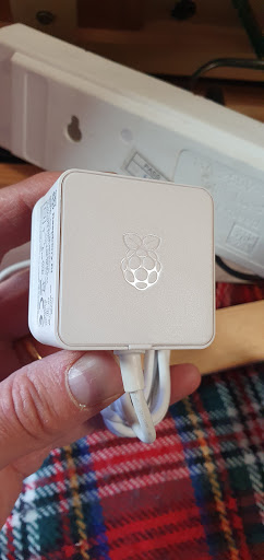
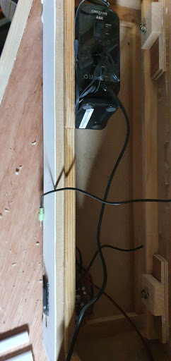
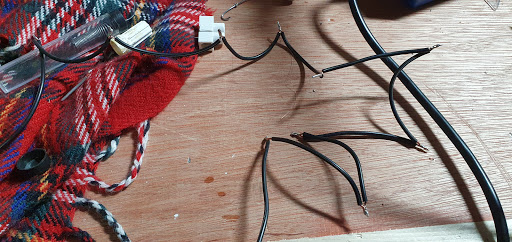
That replaced the Anker PSU I had been using, you can see it on the left here. Earlier I had shortened a kettle lead for the monitor and extended the flying lead for the power strip.
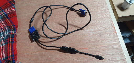
This nest is a VGA cable, plugged into a VGA to HDMI converter, plugged into a HDMI to MicroHDMI converter. Sigh. Pi 3 and below has HDMI, Pi Zero has MiniHDMI and Pi 4 has MicroHDMI!
A test of speakers and screen. The screen had been stored in my workshop for months and I have no idea how it survived that environment. Constantly getting knocked and moved, and terrible dust. It works fine.
Screwed on the nuts for the buttons, this is surprisingly hard. You can buy special tools for this. I recommend those!
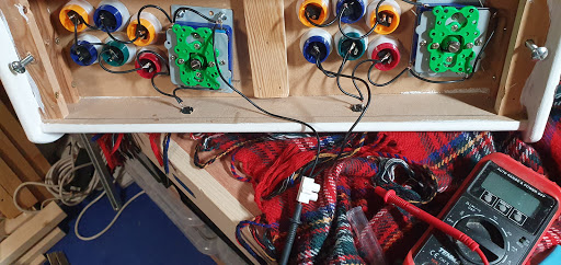
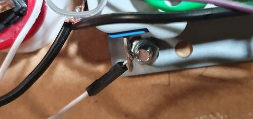
Broke out the soldering iron for the last job of the day. I have all the correct crimps for these terminals, but in the past I had too many had failed on me. I needed this to be very reliable. I know it can still fail but I took a lot of care checking all these joints before I sent it off and I’m reasonably confident it should last a decent amount of time. Here I have added a daisy chain for the ground connections on player two.
Tuesday, 12 May 2020
I LOVE THE SMELL OF SOLDER IN THE EVENING
May 2nd and 3rd coming right up.
Small distraction before I kick-off. Had to make a picture frame for a birthday present for my dear ole ma. Was nice to make some sawdust again. I’m happiest in the sun making a lot of noise and dust. My neighbours actually like me!
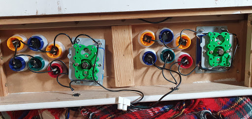
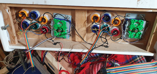
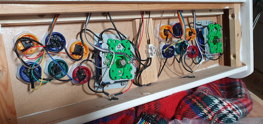
Once that was done it was time to continue wiring the controls. A daisy chain of ground wires. Tedious work cutting, stripping, twisting, fluxing, tinning, soldering each one of these to the terminals.
All done. I made a separate loop for each controller to make diagnosing faults easier.
Checked with my trusty multimeter. No problems at this stage but the wires would be pulled around through the next stages so these will need checking again.
Love these! A few pounds on Amazon. Dupont connectors. Some are male/male some are female/female some are female/male. I think they are all equally lovely 😉
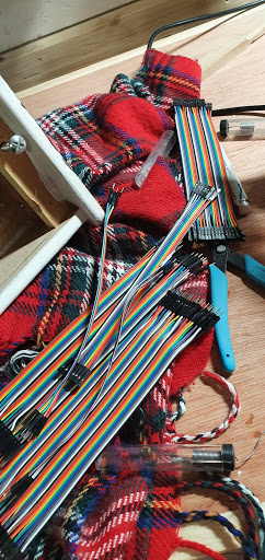
I used a male/male to soldered to each terminal.
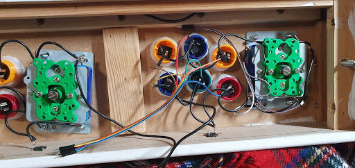
Kept the colour coding the same on each side.
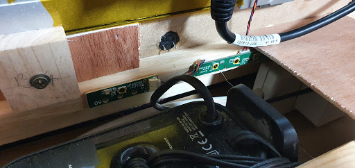
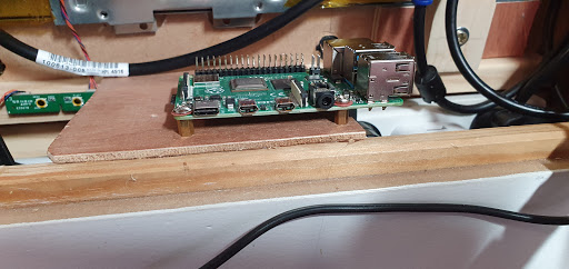
Now I needed to find somewhere to mount the raspberry pi. There is a lot less room than it looks in this case.
Cut a thin piece of ply and glued it in place with hot glue. Also glued on the monitor controls so they don’t move about.

See them better here.
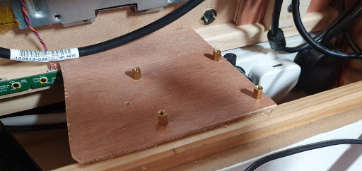
I looked at plastic spacers for mounting the pi, they were really fiddly. I went into my PC screw nest and found some matching height motherboard standoffs. Drilled some holes the right size and screwed them right into the wood.
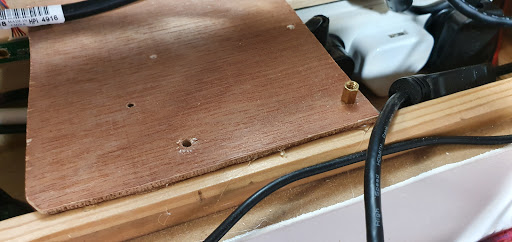
The screws were not very secure so I glued them in place with hot glue.
Oh, look! Another mistake! The power, HDMI, and 3.5mm audio are all facing out. They need to be facing in.
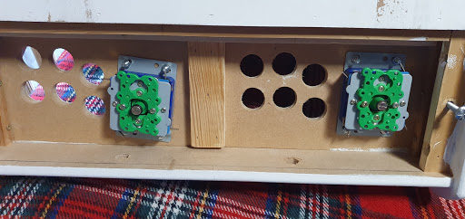
I still hadn’t spotted the mistake. Connected the first wires to the GPIO, these are the start buttons from under the bezel. You can see the back of them covered in hot glue.
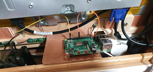
And we caught it just in time. Power, sound and picture all plugged in now.
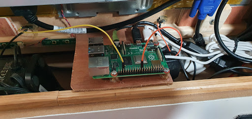
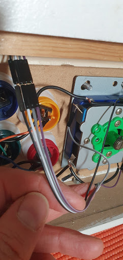
Wires all fed up through the back of the control cavity. They plug into matching female/female cables which are then plugged onto the GPIO connector on the pi.
Spotted a broken solder joint. Would not be the last one!
And all the wires are in the right places.
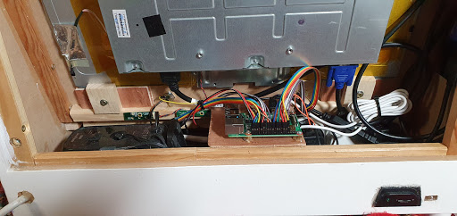
Fired it up to check everything things still work. They do. Next, I need to configure the GPIO drivers to enable the controls.
Tuesday, 12 May 2020
ITS THE END!
May 4th and May 5th. The final post in this series.No, don’t cry. It’s going to be OK. How?Because I’m already planning the NEXT project and it will be done without time pressure and a larger (but not by much) budget. Before finishing the arcade cabinet I was ordered by management to build a new shelf for the kitchen.
There. Now we can get to business.
Now all the wires are in place its time to get the software setup. I found a few guides on enabling GPIO controllers in Retropie, but there were many that were out of date or had various problems. This worked a treat. Pretty easy, just a few lines and then a simple setup. All the buttons and the sticks were detected during setup so I knew they all worked as they should.
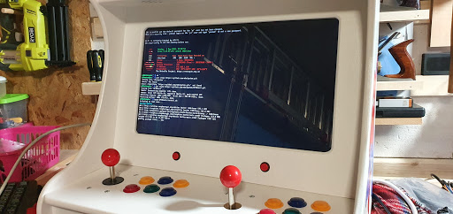
And, after a couple of restarts of Emulation Station, the controllers were detected. The third one is the wired Xbox 360 controller I was using for testing.
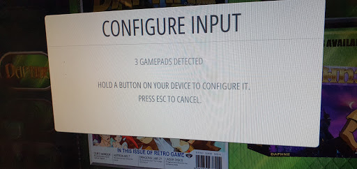
Had some problems getting the right controllers to be active. That was an easy fix: unplug the Xbox pad!
The next morning. Need to get some chores out of the way before I can carry on. Shelves glued together.
After some playtesting, I find that player one has a dodgy stick. Down is intermittent. I pat myself on the back for wiring this with unpluggable dupont connectors. Should be easy to whip this joystick out and fix it.
Then I realise I have soldered all the grounds to the stick. And they are not unpluggable. Facepalm.
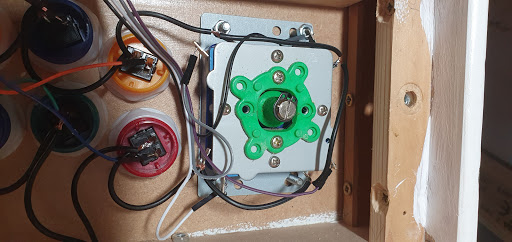
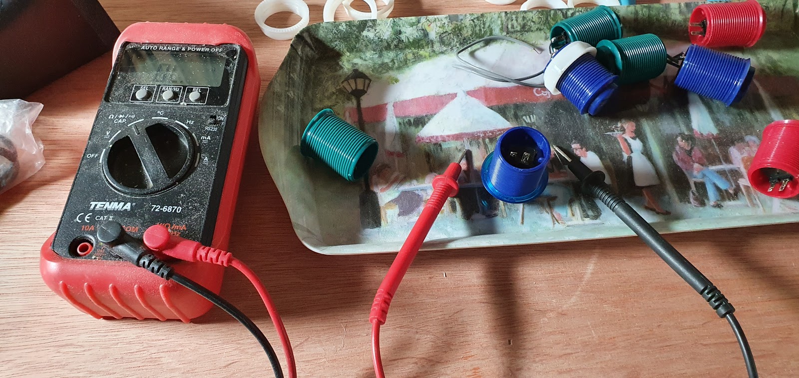
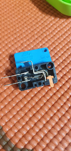
Still got enough room to strip down the stick. This is the errant microswitch. With a multimeter connected to it, I can see it’s not making good contact.
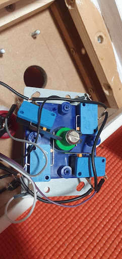
I have this spare, but it doesn’t have the long lever arm the one in the stick has over the switch.
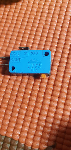
Useful to poke around inside though, I can see how it should look. The faulty one opened just as easy as this, just pry open the cover, and a quick rub over the contacts sorted it out.
Software still needs sorting. The image I am using is by someone that calls themselves by the humourous moniker of Tits McGee. I have to get rid of the boobs. Very young nephews would find them far too funny and I can’t have that. A dig around in the menus and settings sorts that. Also managed to turn off the Irish background music that was good for the first five minutes and then got pretty annoying. I’d be just as annoyed by any national music to be fair, nothing against the Irish.
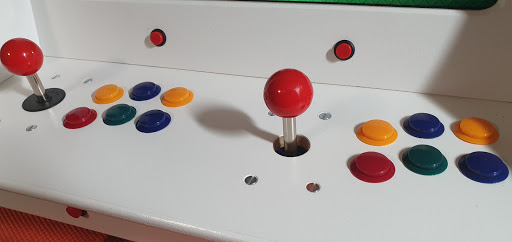
Final touches. Dust cover missing on player two stick.
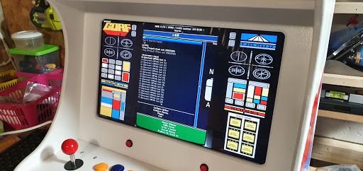
I need to play this again. Selected at random. It’s a Streets of Rage type game called Powered Gear. I had a blast playing this.
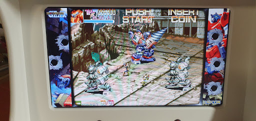
Dust cover robbed from a new stick. I will need to replace that when I get my 3d printer up and running later.
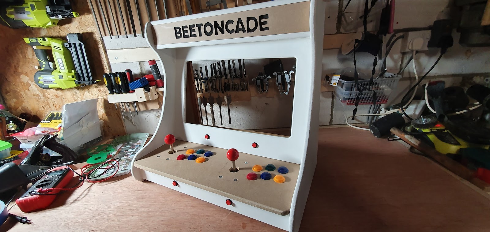
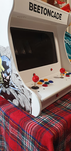
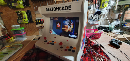
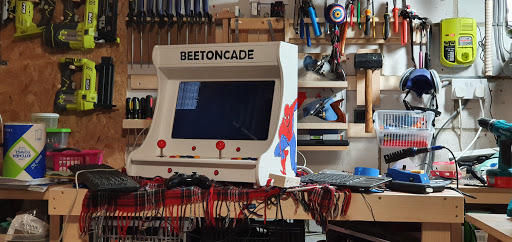
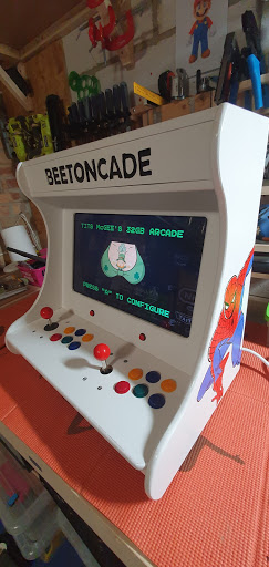
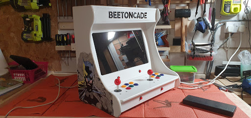
And it is FINISHED.
I spent around £40 on everything I didn’t already own. I had a screen. I had controls.I had speakers.I bought wood (£10)I bought paint (£20)I bought fixings, cables and adaptors (£10)I suppose if you add the value of the previous items I already owned. Screen (£20)Controls (£30)Speakers (£20)A few other cables (£5)The whole thing is worth £115 in parts. Not bad!
But anyway. We are done. That is it, finished.
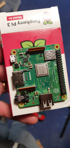
Wait a minute!
Oh look, a pi 3A+ This is going in the next build, so stay tuned. Keep an eye on Twitter or subscribe to this blog if you want to know what happens next! Hope you found this interesting, and thanks for taking a look!
Gus says BYE! (Or “What year is it?”)
Friday, 15 May 2020
An Additional Arcade Addendum
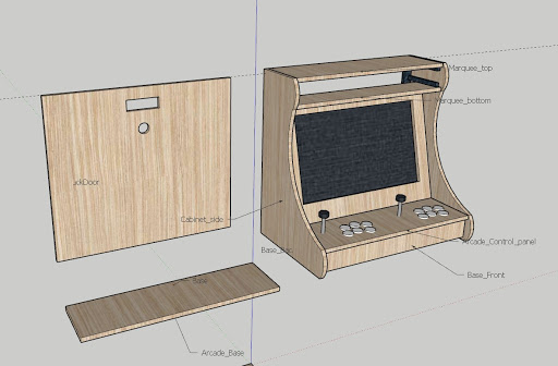
I forgot to add the first part of the build to this log. Apart from the hours daydreaming about it over the washing up the most important thing I missed was the plans. I designed the whole thing in Sketchup (its fantastic) and below you can see the results. I followed this plan to the millimetre and what you see here is exactly how it turned out. Almost. Nearly. It’s about the same size 🙂
Here is a LINK to the Sketchup plans. Feel free to use them any way you wish, but if you do please let me know via my Twitter (@ZZleeZZ) so I can see what you did. Just because that would be really cool. If you do want to use it you might need to adjust it around the screen you use. The one I used was really tight in the case.
- Item one
- Item two