
Elgato Game Capture HD Composite Mod
Incoming mini-project thread!
I have 90 minutes to do something cool.
While I think about what that could be I'll mod this Elgato Game Capture HD so I can capture composite AND audio. Not been able to do this before as I didn't have the right breakout cable.

Up till now, I’ve had to use this very old S-Video to composite converter I’ve had in my cables bin. Probably supplied with an old ati graphics card. But it doesn’t let me connect audio.
So let’s fix that!

Had to abandon this (spoiler – I don’t!). Got to the wiring stage and somehow all the signal pins are now connected to earth.
Possibly the connector I’m connecting to had melted inside due to the soldering heat.
Bugger.
I found a small solder splash in this pic but it’s not that.

I think we might be back in!
Checked the actual resistance to ground from each pin and it was 74 ohms.
Each of these smd resistors is 74ohms…
My meter was being a bit over sensitive.

Anyway!
Back to the start.
The case opens by prying the end caps off. Takes a bit of effort but eventually got them both free without damage.


The lid is lined with heavy metal plates. These can only be for weight, to give it some heft and stop it sliding around on a desk.

The board is held in place with plastic tabs, a bend of the case and it pops free.

And here’s the board freed.
The connector on the left of pic 2 is proprietary and Elgato no longer sells the cables to go in here.
On the other side, pic 3, are the points I’ll be connecting to.


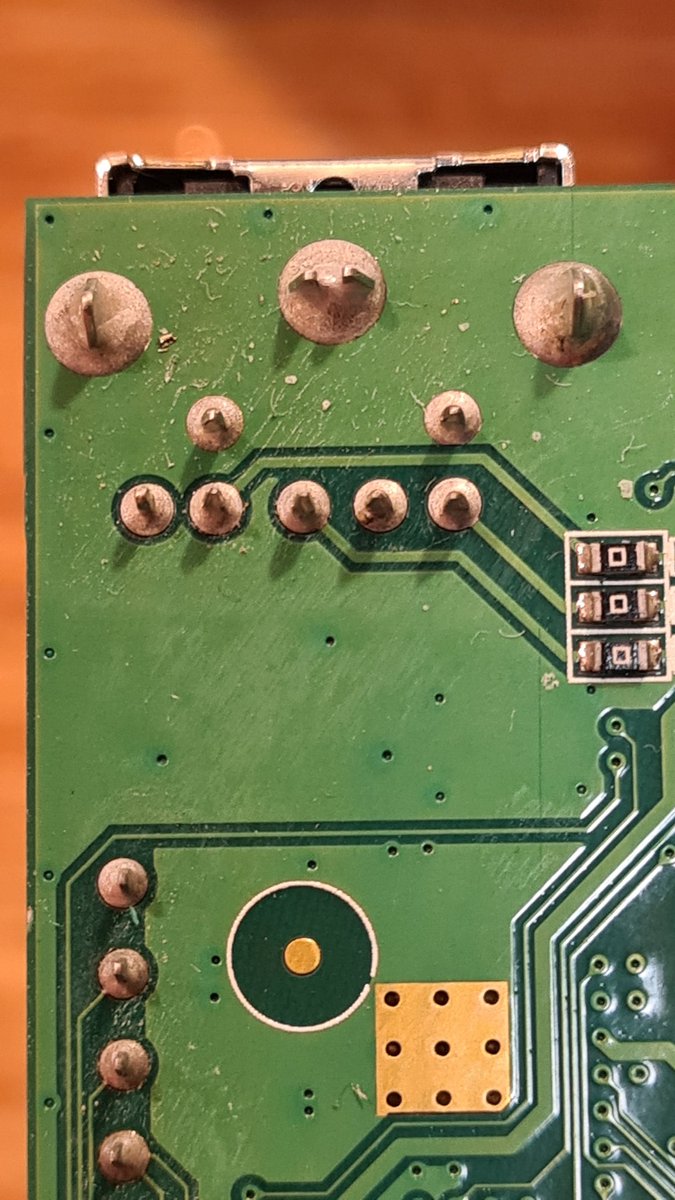
I'll be needing right and left audio and composite as marked. Need to run the cables around the side and up to the top where the new socket will be.

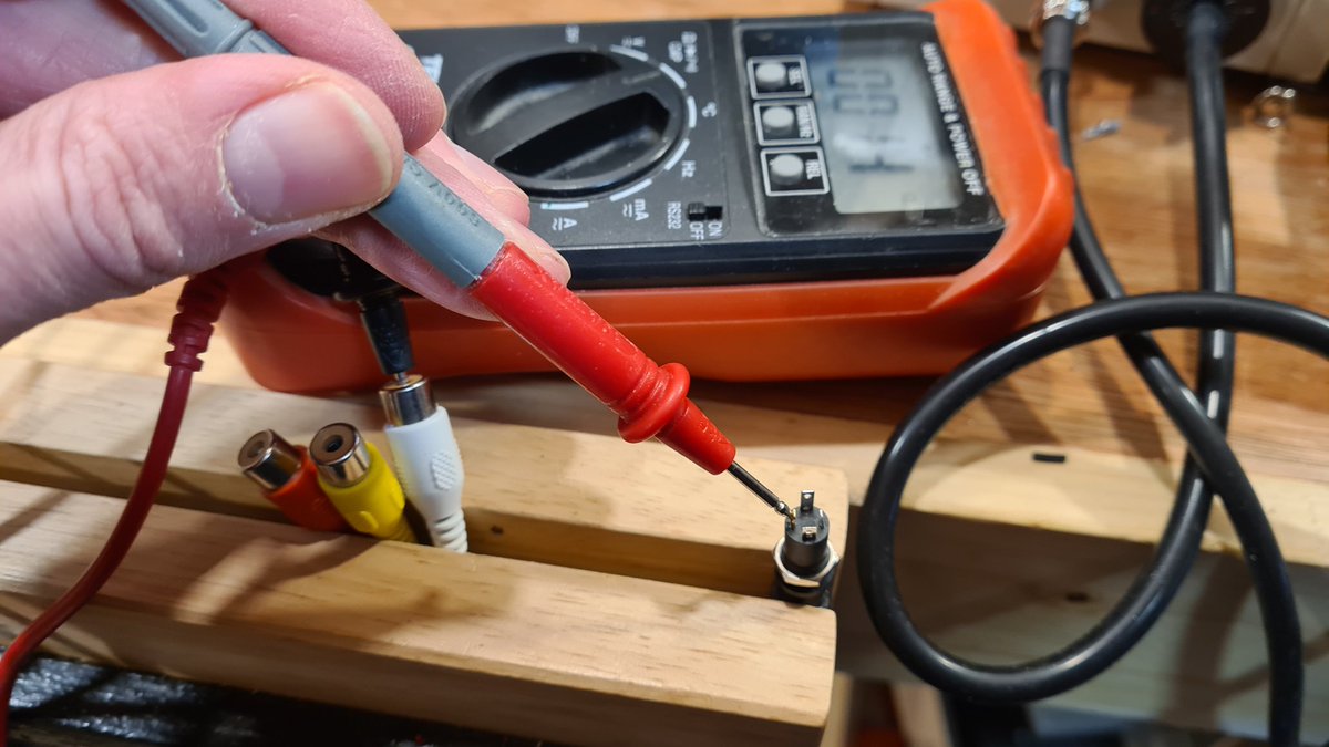
Here's the panel mount 4 pole socket. I used these very successfully with Atari 2600's composite mods.
I had a spare cable to go with this.


These cables often come with various different pinouts, hence why this one is spare, so a quick check to find out which one does what and a handy diagram to guide me when I forget.

There’s space for the socket here in the end cap. I just need to drill a hole for it.
Plastic can be tricky to drill into. Metal bits tend to grab and bite in too quickly, sometimes breaking the part. It’s always better to take a little at a time.

But first, the most important thing before drilling, a bradawl to mark where to drill.


The barrel of the socket is 7.78mm so an 8mm hole is what we'll need.
I'll start with 1mm and go up 2 mm to begin with each step.

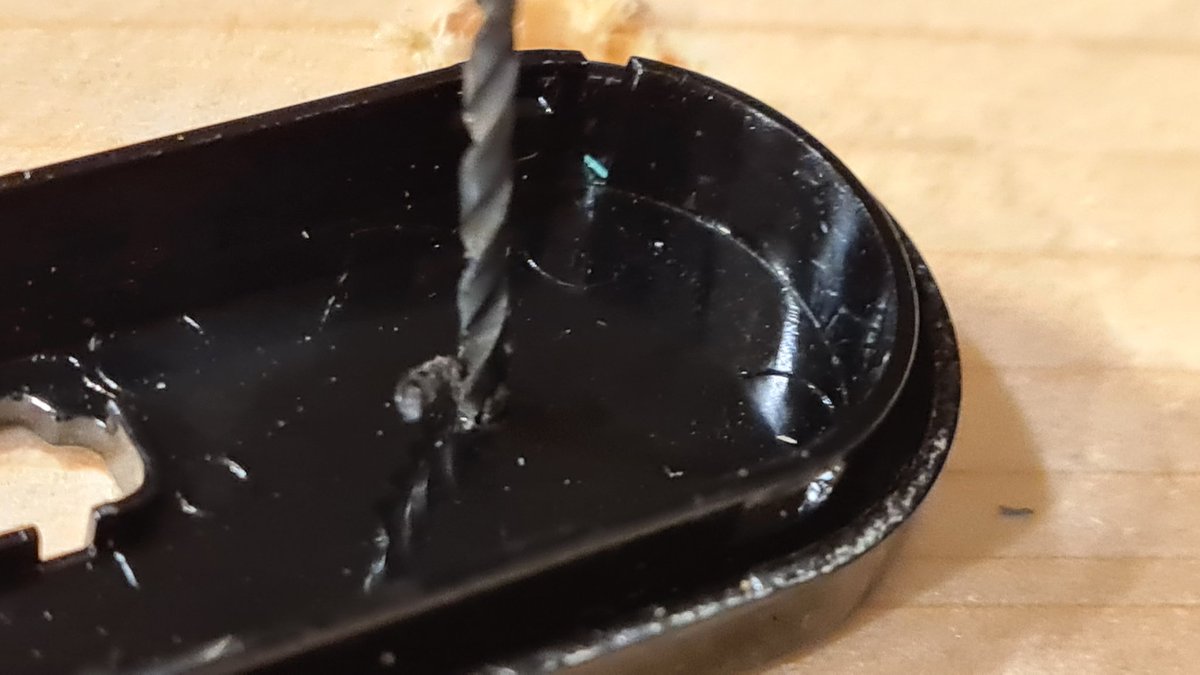

As the hole gets bigger the amount of plastic being removed is greater, so from 5mm I go up in 1mm steps. Until there's an 8mm hole


The hole is a little rough, so a quick rasp with a small round file to remove the bits.
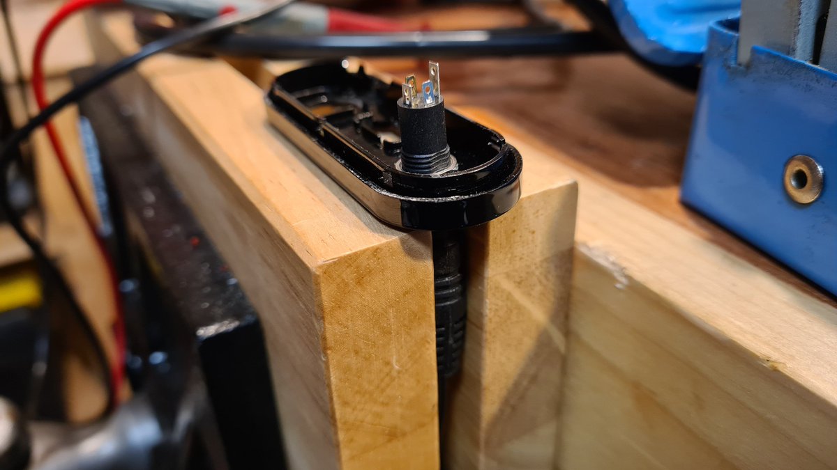
The socket pins have good clearance above the board.


I found some scraps of solid core wire for the connections.

Nearly there!
But now I need to go and eat. So I'll come back to this a bit later.

And I'm back!
Soldered a ground to the side of the hdmi. I did have it in the centre of the 3 via holes you see at the front right, but that ground plane sucked really hard and I couldn't get a good joint.
Board dropped back into the base of the case with plenty of room for wires

Inserted the Jack into the socket while soldering. This helps dissipate some heat to keeps the plastics from going runny.
Terminals tinned ready for wires

Following my extensive diagram, I attached the wires in the right places.
I’m confident at this point!


The case is clicked back together without incident or trapped wire.
The only thing left to do is see if it works!
The best thing I can think of to try it out is my Atari 2600.
Its name is Trashbag, and if I manage to not catch any more deadly pathogens you will see why on my channel…

Judge for yourself!
By the way, I’m playing one-handed with the wrong hand, so be judging the outcome of the mod and not my gamer prowess 😜
I hope you enjoyed the thread!
Originally tweeted by More Fun Making It (Lee) (@ZZleeZZ) on 7 December 2021.