
Speccy Back From The Dead
Did you think because I finished repairing the 2 Speccys in the MEGATHREAD I was done? Haha! Not a chance!
@Ghost82uk asked me to look at this sorry dude.
So another thread starts here!

This poor thing was literally saved from the brink when James stopped is owner from binning it. I like to imagine there was a rugby tackle involved and some frantic scrabbling.
Anyway, however he heroically won the fight it made it to my workbench.
Can it be saved?


This represents the current state of play. Think you can diagnose its fault from here? I'll set up another poll.
#placeyourbets


What the hell's wrong THIS time?
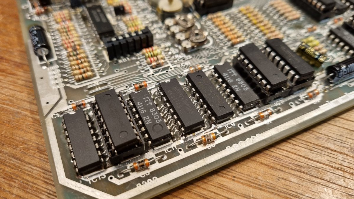
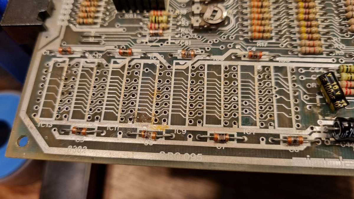
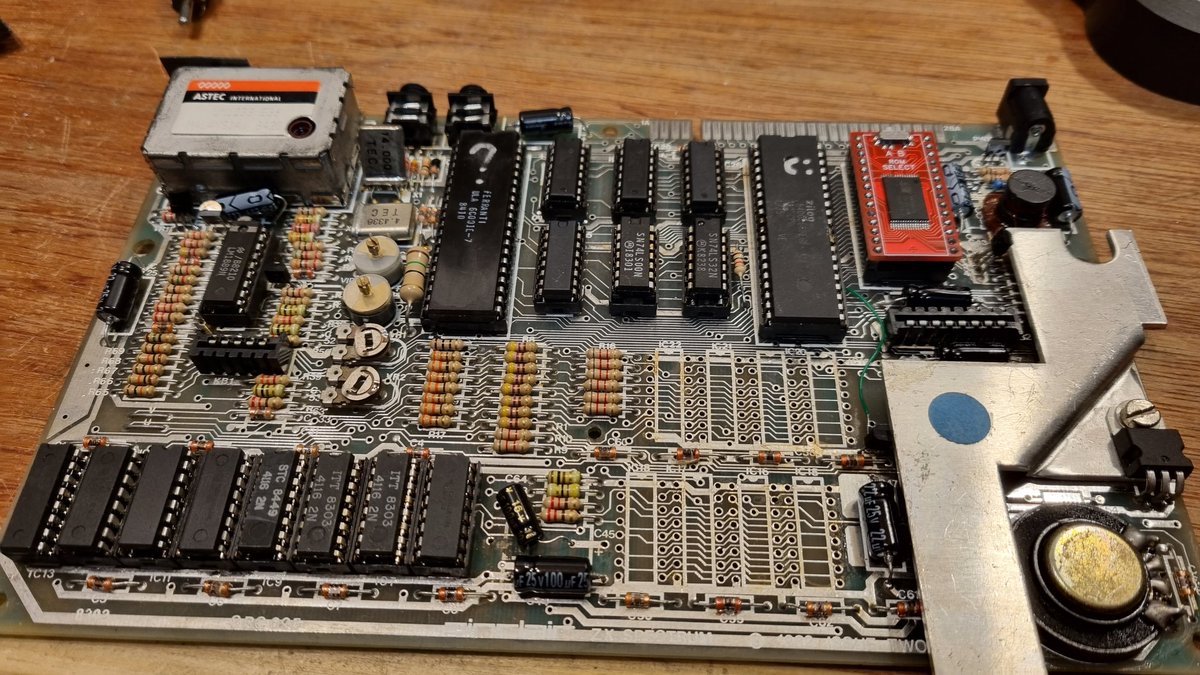
It's an issue 2 again. And it has some problems. 3 of the lower ram, 3 upper ram, 2 logic chips and the cpu have all been replaced. This has had a hard life. Was probably looking forward to a rest in the garbage bin.

The "spider mod" is usually a bit nearer than this!
It's in the right place, I think – need to check that – but the cpu isn't normally socketed. This has been replaced in the past, badly. I worry about the traces beneath the socket. So that will have to come out.


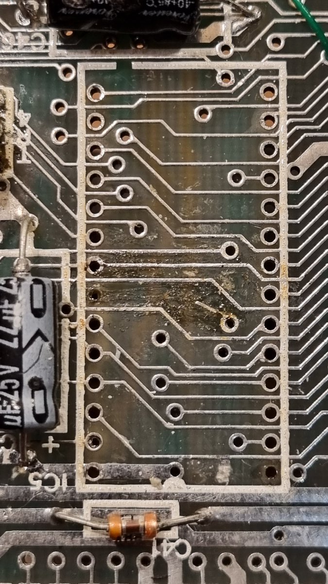
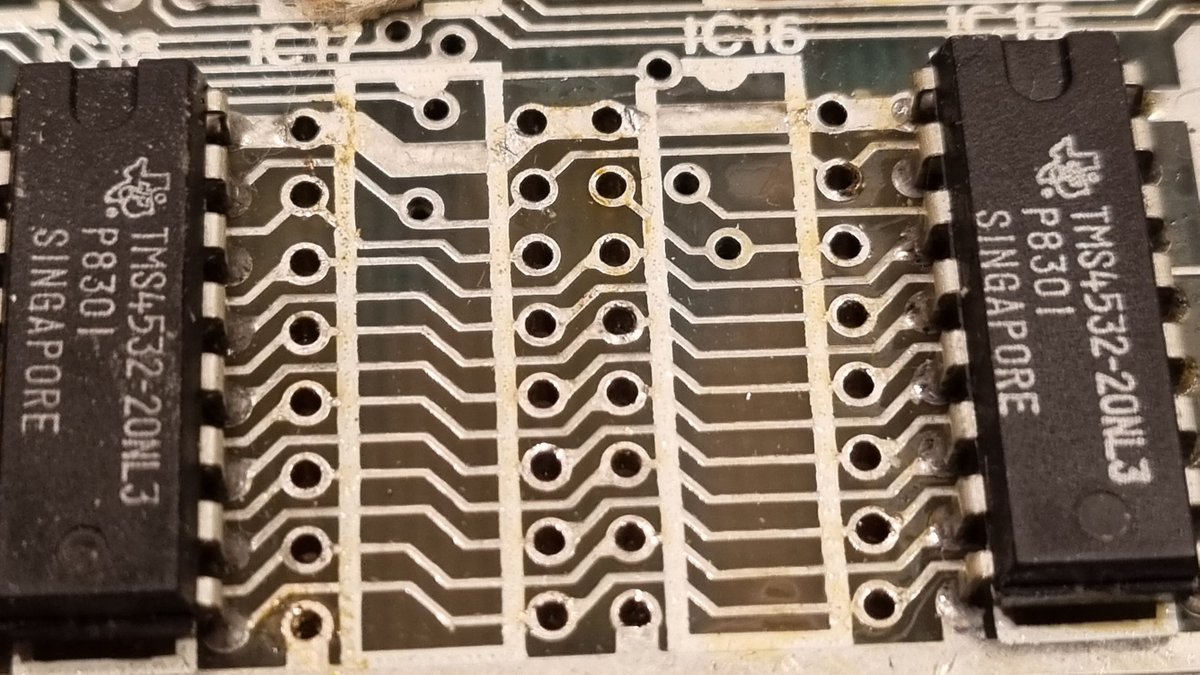
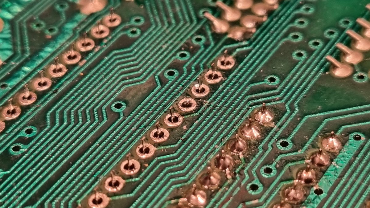
Another area of concern is the video encoder chip, LM1889N.
Topside it looks reasonable,a little too much solder maybe.

This is the other side.
I've no idea what's happened here. Maybe they tried to remove it with braid and just left some behind? Some of the joints on the lower row are starved like they've been wicked. It's a miracle there's no shorts here!


So far I've checked all the socketed ram and logic chips and they're all fine. I've removed the cpu, which was soldered into its socket. That was a pain!
I'll test that in another machine tomorrow. Tonight send your good vibrations and we'll fix this Speccy!
The 4 that voted cpu? ❌
Removed, cleaned, and tested fine.

The socket was a mess so had to be removed. I'm also going to change the spider mod from the top of the cpu to a different position that makes more sense with a socketed cpu.

This trace was already repaired. I've removed that mess and will make something a little neater. The hole will need some attention. If I try to push a pin in there now bad things will happen.

The other side is another mess. It's showing signs of serious mishandling. Probably an unregulated soldering iron and course braid. We've already seen evidence of their braid use elsewhere. Going closer!

A few pads are damaged, this is the worst one. Note the solder mask damage around the area.

And a broken trace to the left of these holes. I'll have to check the footage, it might have been there but damaged before I removed the solder. But I really don't think so.
It's possible this is the fault right here…

Socket installed and traces to and bottom repaired. This trace pictured only went to one of the edge connector fingers, so not the fault. I was hoping that the diagnostic cart would run with this sorted, but sadly no joy. It tries, there's some activity, but not fixed yet!

I'm recording this repair, and I'm quite glad I started, as it's really proving to be an interesting one with multiple areas of the board needing attention. Next up is one part I've not focused on yet – the rom. This has a major bodge wire on the back you can see to the left here

Here's a better pic of the area in question. That bodge is not what you might call optimal.
In fact, take a closer look at the connection on the right. Does that look to you like they didn't scrape the solder mask away?
Ruh-roh!

It came away with minimal pressure and no heat. And there's the tiniest sliver of metal visible, there's a chance this was connected. There's a decent chance this was the problem too. That nasty connection could easily have failed some time after it was done.

What about under the socket? That was a pain to remove with many pads destroyed. And here's the mess for all to see.
That's just… nasty.
This is what happens when you pull a chip from a board without making sure ALL the joints are free. That pad came away and took a trace too.

The next question is – does this ROM still work?
If it does then ask the major 3 chips are functional.

I didn't take a picture (too busy filming) but the rom is fine!
So what's the problem? It could be the dodgy bodge under the rom. Or possibly dead lower ram.
There's one or two other possibilities. But the next thing is repair around the rom and for a socket.
And this is where it gets weird! Second pic is before I cleaned up. And that big resistor leg that looked like a bodge fix? That trace is perfect. No damage at all. Did they fix it for fun?
I still have to fix the other missing trace, but that's a simple one.

Socket inserted. This pad is totally missing. Only joins to the trace to the left. A piece of bare kynar wire twisted around a resistor leg with the end attached to the trace will be a mostly invisible fix.
Camouflaged by the disaster around it.

Diagnostic room inserted and…
Still the same.
I'm thinking lower ram is most likely now. I would have had to sort these sockets out anyway, they were never going to last. And there are other areas that cause concern.
Such as…


What the hell is that?!
Did that just fall there? Is it one of the legs from the old capacitors? A bodge? Want to see what it's supposed to look like?


The white line is the silk screen. That's where that thing was laying. Right across the big fat trace and at least one other trace. Maybe 2.
I'm loving this Speccy. It's like an insane puzzle. One where there's only 8 colours and you can't put the pieces too close together 😜

Removed both capacitors and found why there's a shortage of lead solder. It's all here.
That leg is just floating there only attached to the one trace.
But what's going on with that big trace?
Did they manage to rip that up and then repaired it?


No! (ignore the capacitor)
The traces are totally fine! Pristene!
Pads on the other side are missing so I'm putting radial caps on alternate points. It's that or run massive bodges. One of them is a ground point they managed to vaporise.

One original cap replaced along with the new one. It's left leg in a nearby alternate point.
I don't think this mess is our fault, but I wanted to make sure nothing else would make any new ram I installed instantly explode.

And testing with the diagnostic ROM installed…
Same as it was.
Which is a small victory in and of itself. I've not broken it more.
It's late and about 5 degrees in the workshop, and my old bones are creaking. One more post after this with a sneak preview.
Tomorrow am the lower ram comes out. Only one chip is original, and I don't trust anything that's been repaired on this board. So this lot is out, sockets and all.
Pic 3 gives a hint of things to come…
See you tomorrow! Gnight


Started with the only 2 original lower ram IC's. They came out super easy with zero damage. Both chips test good.


Here's a closer look. No clean up, excellent condition.

On the left is the other original chip position. On the right the first of the replaced chips. You can clearly see the difference.

And an added bonus broken track!
I can see this being a recurring pattern as I dig deeper. I'm betting the main damage is under the sockets.
The third chip tested good too.

Started removing the sockets. Lots of damaged and missing pads everywhere. You can see why I was putting this off!


That's all the chips removed with just 2 sockets to go.

I'm not sure how, but the previous gorilla managed to break one of the power rails.

This one was lifting up with the chip. Not much I could do here. The pads gone on the other side.

And we finally have a bad RAM!
Here's the problem. If I can get all the damage repaired this board will work. I'm sure of it. No way I'll eat those words at all. 😳

All out. There's a multitude of broken traces and lifted pads on both sides. I think I'm going to have to draw this out on paper and note down where the breaks are, then fix them once the sockets are in place
There's the template. Now I'll print this and note where all the breaks are.

The template in action!
Made a bit of a mess but I understand it.

Sockets are all in place now.
But…


There's a lot of work to do here. Lots of missing pads that will need a replacement. Lots of bodge wires.

Bodges complete.
And chips inserted.
Is this the moment we've been waiting for?!


No. 🙄
This looks different though.
I've scoped the ula and cpu. Some of the data and address lines are severely corrupted.
But, what to check next?
Logic?
LM1889N?
Upper Ram?
There's still some work to be done here!

I started pulling LS74 logic chips out and testing them.
Then I stopped. I don't think it's them. I might revisit later to check under the installed sockets.
I was having a read and a blog mentioned tr3, which is over near the lm1889n video encoder chip…

I'll remind you what state that's in. Looks pretty bad even with solder hiding it's sins

I won't lie, if I'd started here I probably would have given up.
That's 7 destroyed pads out of 18.
On the right is another half burned pad where tr3 connects. But things are about to get weird again…

This is the top side.
6.5 pads destroyed here. Mostly different ones to the other side. Miraculously the traces are intact, although in bad shape.


Remember I said it was going to get weird? This bodge wire was hiding under the chip attached to pin 11.
I can't be sure where the other end attached. Possibly 7.
The way I've been taking pics I've flipped the board end to end, so I'll mark the pads in the next tweets.

So it can't be 7. There's no path for a missing trace. Maybe it was 8? There's room there for a trace…
But how can I find out for sure?
Well, what I did was…


… desoldered the same chip from another issue 2 motherboard.
Note the complete lack of carnage under this one.
Also note the lack of a trace.
Pin 11 isn't connected to ANYTHING! Why does it have a wire attached underneath?!


Incidentally, the board I desoldered that chip from is the one I recently scrapped, its in FAR better shape than this one 🤣🤣
Getting late and cold in the workshop, so off to bed. More fun tomorrow I hope!
Will work out which pins I really need and get that chip installed.
I'm satisfied that this lm1889n is now connected as it should be now. In the end there were only a couple of bodges needed on the back.
Testing with that complete and, surprise surprise, still the same.
I'm running out of things to fix. Upper ram and the last of the logic IC's.


I'll start with the lower ram. Sockets out first as they're a little easier to remove and will give better access to the chips on the board once they're out.

This is what's under the 2 sockets you saw. Pretty clean. I don't think this was the same person. Feels like 3 or 4 different people worked on this over the years.
The 3rd socket reveals a little damage. Nothing terrible though. This happens when you remove the solder from underneath but don't mop up what's on those thick traces on the top with braid.

First chip out. Nice and clean.
And we get our first bad chip.


All of the upper ram out. 2 of them faulty.
I'll leave this unpopulated till its fixed. It should just function as a 16k.


And with all the ram out of the way… Exactly km the same problem.
I've also removed and tested the logic chips and all of them are fine. There's still 2 sockets to remove and check under, but I'm losing confidence now.
I might need to step away for a little while.
Almost broke the thread!
Won't be the only thing I've broken today either 🤣
Oh. This is bad news. For my sanity sake I decided to retreat all the 3 main chips again. The ula has gone bad. There's a slim chance it might be OK in another board, I can't remember which one I checked it in before.
*retest
OK. Running out of things to fix. There's the dc conversion, which is a bit messy but works.
And the sockets I didn't change under the logic chips.
So let's take a look at the sockets.
There's some really scabby solder under there. My poor desoldering station has certainly earned its keep this week!


Remember webbed things got weird before when I uncovered bizarre crap under things on this board?
Well that second pin I just desoldered… Well there's no pin there. Did it get cut short?
The one next to it was also missing.
Very strange.

I have had to close my mouth manually.
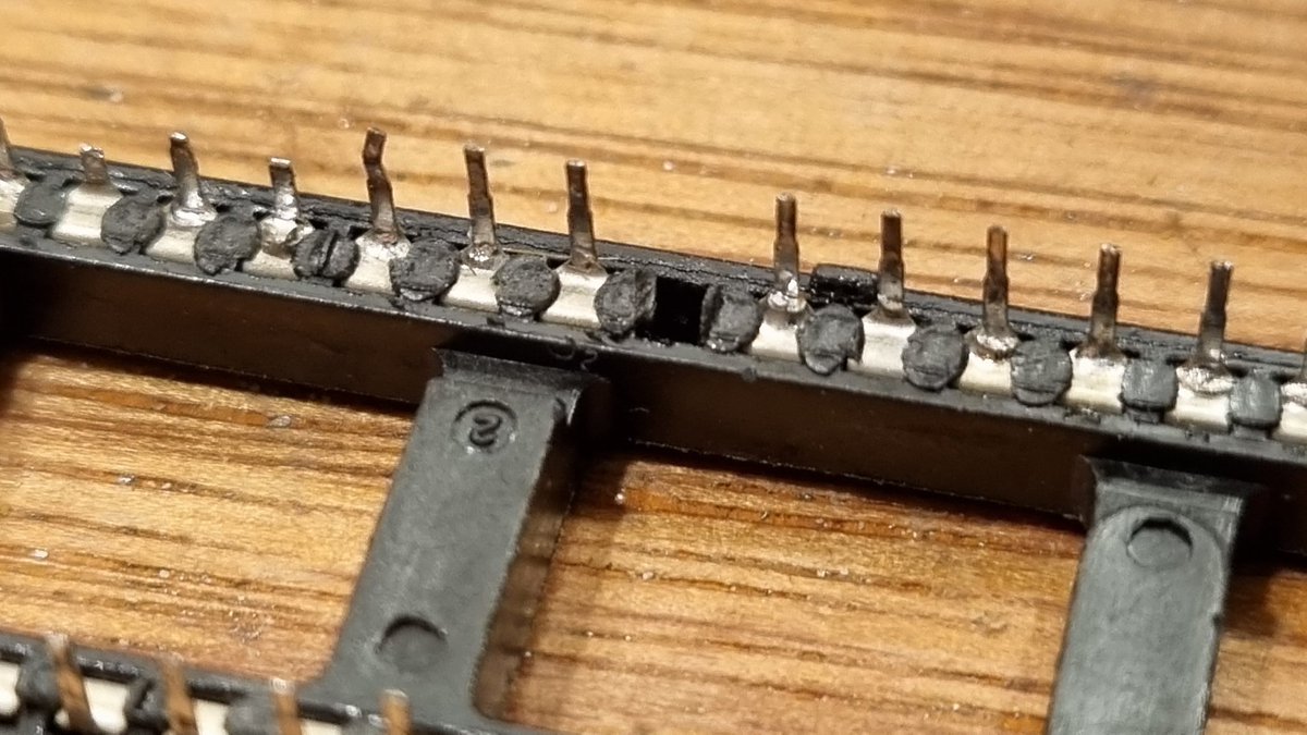
That's how this socket was soldered into this board.
There's still a chance those pins would make contact with the traces and pads on the top. So this still might not be the fault.
Please let that be it!

Nope! Still broken!
ARRGHHHH!
Breathe….
I'll have to leave this here tonight. It needs to ferment, then something will occur to me.

Always have a plan.
The last thing to check is the damaged area around tr4. So I'll remake that today, and then check around under the heat sink area.
After that I'll get out the schematics and start tracing connections between components.
Might be a little less exciting today!

Going back to that socket with the bent pins. This is where they were laying. That was probably causing a few problems!

I'm no electronics engineer, but I'm fairly sure resistor colour bands don't include 'big burnt bit'
Don't get your hopes up. I bet that sucker is still working


Haha! Incredible. It tests at 15ohm and that's what's supposed to be in that position.
I've found so many things on this board that on any other day would have been the cause of this computers problem.
And each time it's not!
Onwards!


Have remade the tr4 area, no pics, soz.
Decided to take a look at the ula socket. I'm sure it's original, but some of the solder looks dodgy. It could also be a bad socket.
After removing some of the solder I found broken pins underneath. Could this be it?


This was the state of the socket. I don't understand how this happened. Can a socket corrode whilst embedded in solder?


This missing pin stayed in the board. So no mystery there.
It's a nice clean set of points. There's no damage under here, so the socket is definitely original.

Faulty ula reinstalled. It should be good enough for testing, I'll try my modern replacement later too.
And, still the same.
Or is it?
You can see here the real Sinclair ROM is installed. I'm not convinced that's making the best contact with the socket.
Try the diagnostic rom?

The diagnostics rom has a switch to choose between 2 different diagnostic options. In one position the border flashes loading style and that's all it does. And in the other it just has the same image as with the Sinclair ROM.
Or does it? 😜

Just before I switched it off in disgust the border changed colour from magenta to yellow. I'd seen this before but put it down to random glitch. I left it for a few seconds and then it did this!
That's showing a fault on the lower ram!
Actual progress! 😁

That line indicates either ic7 or 12 is faulty, so I swapped them. The line didn't move, so it's not the ram chip. Possibly the socket. Possibly something faulty upstream.
But this is really good news. I've now got something solid to track down.

Didn't have the longest time to work on this today.
Popped that socket back out. Turns out it's not the one indicated by the diagnostics.
Oh well. While I was here I made some improvements to the bodges. There's a lot of breaks in this area.

I figured it must be the other end, ic11, diagnostic results did not support this. In fact the diagnostics became corrupted. Sometimes saying 4 chips were faulty, and other times a different one.
I put the sockets back. It's not the ram.


A couple of examples of strange results


Then it started getting really weird.
I realised when I recorded this that the Retroleum logo and title is clearly there on the screen.
That's a promising sign.
Took all the ram out and tried it and the diagnostic still ran!
Still have an inconsistent result. I'll have to start looking elsewhere.


Finally busted out my new scope. I'm still learning this stuff, so if you experts it there see anything obvious please weigh in!

I think this is the RD line. On a normal speccy that p2p is around 5.4v. This is 7.8v,that doesn't seem right. Some of the data lines are also doing similar.
Some other readings are marginally wrong. Nothing on d14 or 15 which indicates the rom.
Also halt is low all the time.

The bulk of the square is around 5v. But there's a 1-2v drop at the start of the trough. So that looks like something is grounded that shouldn't be? Wish I knew more about this.
Had to quit for the night as was so tired I was making stupid mistakes and not taking pictures or video.
But…
I found TWO shorts.
One of them between CAS and a data line. Fixed that one, put it back together and then found another. So tomorrow I'll fix that one and it'll work!
Maybe.
Update time!
Didn't get as much time to work on this today, but made some progress. Found that one of the stupid tired mistakes I made last night was plugging the diagnosis rom in wrong. No damage.
Also had wired one bodge wire wrong on the lower ram.
Don't work tired!

Put all that right and I get consistent results. It still thinks ic7 is broken.
But now it sees when I remove another ram chip. That's really good.
Then tonight, after a lot of poking around, I find address line 12 is shorted to ground.
That's it there under the cpu socket.

Before I took out the cpu socket again I have it some thought. This is shorted to ground and the pins 1 and 3 on the cpu socket are not ground. Can't be that.
But under ic26 to the left they are close.
And look what I found!
Sneaky bugger!

This looks promising!
That's the best image so far!


But it STILL says ic7 is not working. Something else I missed?
For this I busted it the schematics.

Data line 1 comes out of pin 21 of the ULA and is supposed to connect to pin 3 of IC7. But my continuity test shows it doesn't. I followed the traces and they all seem fine. The only ones I couldn't see were running under IC6 and IC7…

Nothing under IC7.

But next door under IC7…
My fault, I should really have spotted that before.
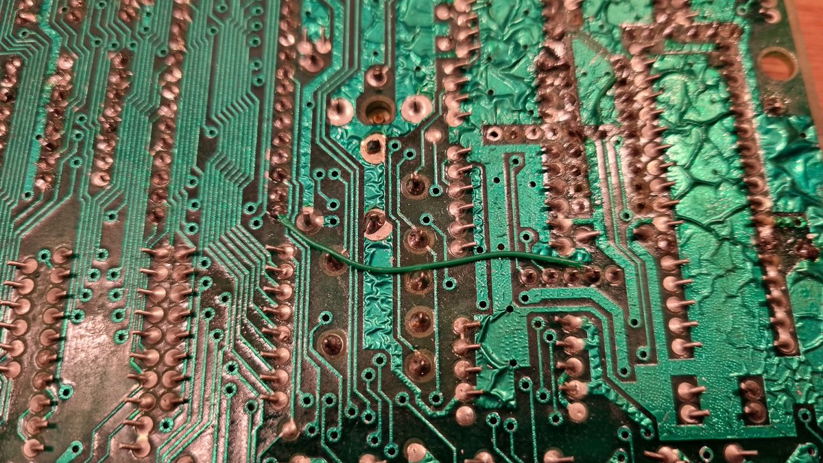
Bodge wire installed on the back.

I'm getting much further in the diagnostics now.
But there's still a memory error.
I'm out of time tonight, I'll be back to this tomorrow and I will bloody fix it this time! 🤣


I couldn't resist having another poke around.
More schematic perusal and trace… er… tracing and I found yet another break under the ram. Fixed with another bodge wire and…

It works!
It's still got a way to go though. There's a persistent memory error that moves around. It will indicate one chip which I'll replace and then another seems to go bad. All the chips test good in my ram tester.


It's so close now. One more fault to track down and the upper 32k ram to install and it will be back from the dead.
Back for more tomorrow!
It's still not 100%, but it's getting closer all the time.
Now tracking down the source of some slightly high peak to peak voltage readings.
Once I get it working well I'll then put the other 32k of memory back and we can move onto making it pretty again.

7.8v p2p is not right. That's the read line between the ula and cpu, also heads off to ram.
That spike in the trough is there on ground, like interference.
I've ordered a set of new caps. Will wait for those and then try again.

Here's the ingest folder for all the footage I've taken. That's gonna take a while to edit!

HOLD THE PHONE!
Are resistors supposed to be that crispy and brown?
This was not there earlier, probably something that's happened during testing.
It still works as a resistor but it's supposed to be 15ohm and it's measuring at 21. I'll replace it in a sec

That's resistor r64 which sits between +5v and pin 19 of the ula. Also goes to the keyboard connector.
I've no idea how that got shorted.

Well then…
Still something screwy going on. This is what happens if I plug in a working ULA. Previous video was the modern Nebula version
Bingo!
Got this prefect ULA from @The_Real_Riggz today.
It's prefect because its exactly the same as the one it's replacing. This is good because I just realised that the horrible blue flashing in the previous tweet was down to the variable resistors on issue 2 boards.

These resistors need to be tuned into different revisions of ULA.
As this was the same it worked without touching them.
But there's still something odd going on.

Sinclair ROM installed and Dandanator connected it reports a ram error.
Turn it off and back on and…


Which points convincingly to ic3 and 4.
They're the only logic chips on the board right now.
So I swapped then with some other ones.


And it started to test OK!
I'm still not convinced though.
I think there's an intermittent fault hanging about.

Back to the diagnostic rom for further testing.
Seems fine for now. I'll test some more over the weekend while I wait for some parts to arrive.


Started swapping caps out.
Can't get the nice cheap black ones any more sadly. So we're going to pretend that having the right colour caps on the inside of a computer that's not exactly easy to open is, in fact, very important!
😜
I'm now preserving our spectrum heritage!

So with that important mission in mind I've fitted this extra efficient switching regulator.
These are ace. Much easier to work on the Speccy without that pesky heatsink.
Can save the spectrum from dodgy power connections too.


And it's saving the planet. I have another issue 2 here that draws more than 4x the current.
And in that one all that extra energy is dumped inside the non vented case as toasty heat.

For testing purposes I've replaced the lower ram with a modern module. This might also be contributing to the lower current draw as it only requires +5v rather than the +5 – 5 and +12v the original 4116 dram chips need.

Next job on the list is sockets for all the upper ram.
I made a video not very long ago in which I said I didn't really like sockets. I've very much changed my mind now.
Here's that video for the curious.
It's amazing how much I've learned since that video. I would do almost all of it differently. Some of that comes from some major tool upgrades, but having fixed a whole bunch since then I'm just further along. We all have to start somewhere and get the mistakes out of the way!

Anyway!
One thing this board has taught me is to do one thing and then test.
So, after each socket is soldered in place im plugging the speccy in and testing it.

It does show things down a bit, but the benefit of knowing exactly which one flowed a solder bridge onto a track near a pin is worth it and would have saved me days work on the lower ram


I've been through and tested each connection, also testing for shorts between each pin and the ones around it.
That done in testing each of the ram IC's I removed just to make sure.
I'll put 2 new ones in too replace the ones that went faulty.


Side note : remember my concerns with the high p2p voltage? I scoped an issue 4s and it was the same. It even had the same word interference I saw on the 2.
I'm much more confident this board is nearly fixed.

Upper ram installed. I've dug around and matched it all.

There's a shock 🙄
Oh well. Too tired tonight to start chasing this down. I had a feeling this had one more big surprise for me!

Who am I kidding.
There's no way I'd sleep without at least checking the lines between the logic and the upper ram

Well, that was frustrating. The schematics don't actually match the board. Checking against another issue 2 just to make sure I'm not being daft. Definitely going to leave this for the night.
That's why I should just quit and go to bed when I'm tired. As soon as I woke up this morning I realised I'd had a complete brain fart counting the right side of the chip the wrong way up.
Took a whole day off. Needed to set up new vr headset for family use.
But now I'm back at the coalface!

Right! I can't do the testing I wanted to do tonight as I realised since I just sold my old analogue oscilloscope I've now only got 1 probe. New ones on order. So for now I'm going to do the dc-dc mod I've been meaning to do.

I need to attach a 4.7uf cap between c34 and r58 (top resistor)
Remove R60 and replace it with a 270ohm resistor.
Second pic is my issue 2 with the mod done.
I wonder if this might clean up the noise on the board?


Mod complete. No change.
Tomorrow the scoping starts for real!

Another days delay. Somehow my Amazon delivery of the new scope probes defaulted ITSELF to a slower method without me realizing it. Cancelled the order and remade it with next day delivery. Very frustrating!
Spent a good chunk of the evening dual wielding scope probes.
Have tested probably 50% of the chips. Starting with the likely stuff, ram and logic. All working as it should so far

I did get excited at this one.
But turns out the scope was only triggering on one trace.
I'm still not familiar enough with the workings of a DSO to know how to make it trigger on both traces.

Progress!
Well, I hope it is.
The bottom trace is RFSH on 28 on the cpu of a working speccy.
The top trace is the same pin on the poorly machine.
That top trace looks a lot like the data lines on this one. I think we've found the short.
Question is where is it shorted?

That line runs through a few places. A resistor and capacitor and then to pin 4 on the lower ram. After that it comes back to ic3 pin 1 which you can see here with no chip.
Could be under the lower ram, the cpu or ic3. I need to review the footage to see if I can spot anything.

There's also a chance this difference is down to the very slight differences in these boards. Even though they're both issue 2 there are some different components in alternate positions.
But that cpu pin 28 doesn't look right…

Previous possible faults turned out to be idiosyncrasies of different cpu's, board revisions and me reading the schematics wrong.
I went through every pin, on every IC comparing the traces to a working board, side by side.
Many a wild goose was chased.

This for instance. These are the same signal. On 2 boards. They look different. One could be thought of as bad. But they're both valid logic signals. On a Spectrum that is.

Again. Same pin on 2 different boards. But this one is down to me not knowing how an oscilloscope works 🙄

There were a few other gooses. And if I'm honest I was wondering if I would have to rip every chip and socket off the board and build it from scratch to find the problem.
But then I thought I would asproach the problem in a logical way. By taking all the logic chips associated with the upper ram off the board.
Each one revealed nothing. No bridges. No breaks. But wait what's that on pin 10 of ic26?
Looks like something on the via?

Can you see it?

How about now?
When I tested all these before putting the sockets in my probe must have rested against the end of the trace.
From now I'm going to check with a microscope!

When I saw this screen…
Well, you'll have to wait for the video on my youtube channel for THAT reaction!
This has been an EPIC repair.
Now I just have to wait for a keymat from ZX Renew to arrive and put it all together!
Wonder if it has any more surprises for me? 🤣


Haha! That didn't last long. Two columns of keys don't work. And that's a brand new membrane and the second one I tried.
I told you it still wanted to play!

I knew it would have one last trick for me and it didn't disappoint!
There's a problem with the keys…

Pin 2 of the keyboard connector you see here is supposed to be connected to pin 20 of the ULA.
But its not…

You can see the trace indicated by the small hand. It runs under this variable resistor…

That's it coming out the other side.
Somewhere under that VR is a break. Can you see it?

See it now?
That happened when a gorilla jammed a screwdriver into that pot to adjust the colour balance and managed to tear the trace right out.
Absolute neanderthal.

Keyboard fixed.
Second pic is so you can play "Spot the Bodge"
There are MANY.

With the keyboard fixed and case parts in the post, games loaded and tested via Dandanator cart, the only thing left to test is loading a game the old fashioned way.
I'll save that for tomorrow.
I'm going to play on my bed and not sleep for 8 hours now 🤣
Games loading perfectly from audio!
This #ZXSpectrum is now FULLY OPERATIONAL!


HAHAHAHAHHAHAHAHHAHAHAHAHHAHAHAHHAHAHHAHAHAHAHHAHAHAHAHHAAHHAHAHAHHA!
That's what I saw when I turned on this little bugger and ran one final diagnostic test!

Checked all the chips were pushed into sockets. Checked for shorts. Nothing.
Took all the lower ram chips out and put in this module.
Passes with flying colours… Hmm


Put one chip in. Sees its as good. 2 chips? See the image.
I go through all of them testing one at a time. Each time it sees the chip as good.


Then I put the last one in. By the way, I'm cleaning all the legs and making sure they're all straight and perfectly inserted.
Ram failure. All chips.


This is my exact reaction.
It's likely there is still something wrong under one of the lower ram sockets that's causing this. The module doesn't use all the pins and it looks like it bypasses whatever is wrong.
I'll check to make sure it's OK, but I don't fancy taking all that out AGAIN.


So I'll swap the module for the ram, they're not that expensive and I'm happy to gift it to you @Ghost82uk as a thanks for all the brilliant fun I've had with this.

A last minute tune up of the colour balance and dotcrawl before it gets packed up and sent home.


It might not be the prettiest ever, but it's going to be a machine I remember fondly for a long time.


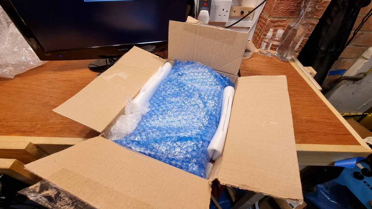
See ya little dude.
The End.
Originally tweeted by More Fun Making It (Lee) (@ZZleeZZ) on 20 January 2022.